


19
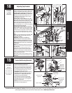
Please Do Not Return This Product To The Store. Contact your local Wayne-Dalton dealer. To find your local Wayne-Dalton dealer, refer to your local
yellow pages business listings or go to the Find a Dealer section online at www.Wayne-Dalton.com
Tools Needed:
Tools Needed:
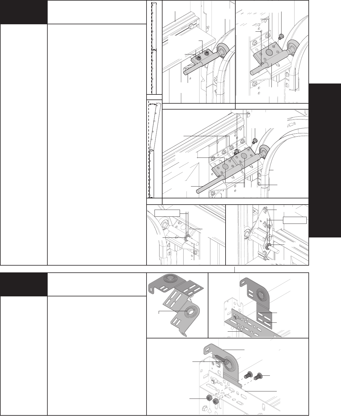
INSTALLATION
Correct
Incorrect
(C)
(B)
Top section
(1) 1/4” - 20 X 9/16” Track
bolt and (1) 1/4” - 20 hex nut
(1) 5/16” - 18
Nut
18
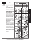
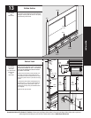
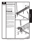
With horizontal tracks installed you can adjust the top
brackets. Vertically align the top section with the lower
sections. Once aligned, position the top roller in the
adjustable slide(s), out against the horizontal track.
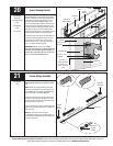
FOR WINDLOAD OPTION CODES (A): 1100 OR 1120:
Maintaining the slide’s position, tighten the (1) 1/4”
- 20 flange hex nuts to secure the slide to the top
bracket. Repeat for other side.
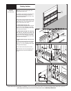
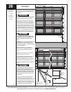
FOR WINDLOAD OPTION CODES (B): 1101, 1102,
1103, 1104, 1121, 1122, 1123, 1140, 1141 OR 1143:
Maintaining the slide’s position, tighten the (1) 5/16”-
18 nut to secure the slide to the top bracket base.
Now lock the slide in position using (1) 1/4” - 20 x
9/16” track bolt and (1) 1/4” - 20 hex nut through any
aligning hole. Repeat for other side.
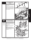
FOR WINDLOAD OPTION CODES (C): 1124, 1125,
1142 or 1144: Maintaining the slide’s position, tighten
the (2) 5/16” - 18 nuts to secure the slides to the top
brackets. Now lock the top slides in position using (2)
1/4” - 20 x 9/16” track bolts and (2) 1/4” - 20 hex
nuts through any two aligning holes. Repeat for other
side.
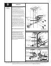
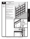
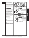
NOTE: If you have windload option codes 1121, 1122,
1123, 1124, 1125, 1141 and 1142, pushnuts are
required to be installed.
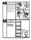
IMPORTANT: ACCURATELY POSITIONING THE
PUSHNUT ONTO THE ROLLER STEM IS CRITICAL.
ONCE THE PUSHNUT IS PUSHED ONTO THE ROLLER
STEM, THE TABS MAKING CONTACT WITH THE STEEL
SURFACE, WILL MAKE IT DIFFICULT TO REPOSITION
THE PUSHNUT.
NOTE: When positioning the pushnut onto roller stem,
ensure the tabs on the pushnut are pointing away
from roller stem.
Starting with the top bracket assembly, slide (1)
pushnut over the roller stem and push the pushnut
towards the outside edge of top bracket assembly
leaving 1/4” spacing between the outside edge of top
bracket assembly and pushnut.
Repeat same process for the end hinges on the left
hand side of door, then repeat same process for other
side of door.
Adjusting Top Brackets
7/16” Wrench
1/2” Wrench
Step Ladder
Tape Measure
Horizontal
track
Top bracket
slide
Short shaft
roller
(2) 5/16” - 18
Nuts
Top bracket
slide
Top section
Horizontal
track
Long shaft
roller
Top bracket
slide
Top section
(2) 1/4” - 20
Flange hex nuts
Short shaft
roller
Top bracket
slide
Horizontal
track
(2) 1/4” - 20 X 9/16”
Track bolts and (2)
1/4” - 20 hex nuts
Top bracket
assembly’s
(A)
Roller stem
Pushnut
End Hinge
1/4” spacing
Pushnut
Roller stem
Top bracket
assembly
1/4” spacing
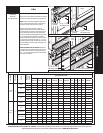
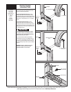
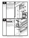
Torsion End Bearing Brackets
End bearing brackets are right and left hand.
Break the end bearing brackets apart.
Starting on the left hand side and using the upper
slots in the end bearing bracket, position above
the flagangle and secure the end bearing bracket
to the horizontal angle using (2) 3/8”-16 x 3/4”
truss head bolts and (2) 3/8”-16 nuts.
IMPORTANT: END BEARING BRACKETS MUST BE
ATTACHED THROUGH THE LOWER SLOTS ON 12”
RADIUS TRACK. 15” RADIUS TRACK MUST USE
THE UPPER SLOTS ON THE BRACKET.
Once the bracket is secured to the horizontal
angle, secure the top of the end bearing bracket
to the jamb using (1) 5/16” x 1-5/8” lag screw.
Repeat for right hand side.
NOTE: Right and left hand is always determined
from inside the building looking out.
Step Ladder
Power Drill
Ratchet Wrench
7/16” Socket Driver
9/16” Socket Driver
9/16” Wrench
Left hand end
bearing bracket
Upper slots
Used on 15”
Radius track.
Lower slots on
12” radius track.
19
Horizontal
angle
Break the
end bearing
brackets
apart
(1) 5/16” X 1-5/8”
Lag screw
(2) 3/8”-16 X 3/4”
Truss head bolts
(2) 3/8”-16 Nuts
Left hand end
bearing bracket
Horizontal
angle