


8
Please Do Not Return This Product To The Store. Contact your local Wayne-Dalton dealer. To find your local Wayne-Dalton dealer, refer to your local
yellow pages business listings or go to the Find a Dealer section online at www.Wayne-Dalton.com
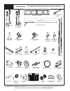
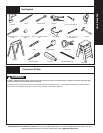
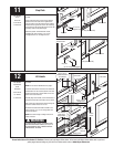
Tools Needed:
Tools Needed:
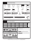
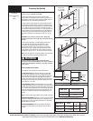
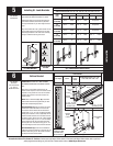
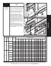
NOTE: The following (JB-US) denotes a slotted jamb
bracket.
Measure the length or the vertical track. Using the
jamb bracket schedule, determine the placement
of the jamb brackets for your door height and track
type.
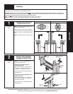
Loosely fasten the (JB-US) jamb bracket to the track
with a 1/4”-20 x 9/16” track bolt and nut.
Tape Measure
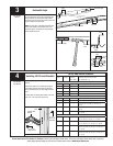
3
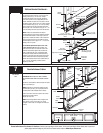
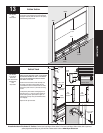
Position the horizontal angle as shown. Place tabs
of horizontal angle in the key slot of horizontal track.
Using a hammer, tap the horizontal angle towards
the curved end of the track until the hole in track and
angle are aligned. Set tracks aside.
NOTE: For larger doors, a full length horizontal angle
may be spot welded to the horizontal track. If the
horizontal angle is not welded, the horizontal angle
will be installed as shown.
Horizontal Angle
Hammer
Horizontal
track
Horizontal angle
Horizontal angle
Horizontal track
Hole
Hole
Tabs
Key slots
Horizontal
track
Tabs
Horizontal
track
Horizontal
angle
Key slots
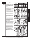
(JB-US) JAMB BRACKET SCHEDULE
DOOR
HEIGHT
NO. OF
SECTIONS
NO. OF JAMB
BRACKETS
(EACH JAMB)
LOCATION OF CENTER LINE OF JAMB BRACKETS
MEASURED FROM BOTTOM OF TRACK
(ALL DIMENSIONS ± 2”)
WINDLOAD SPECIFICATION 1101, 1102, 1120, 1121, 1122, 1140, 1141, 1143
6’-0” 4 1 33 1/2” (JB-US)
6’-6’’ 4 2 34” (JB-US), 56” (JB-US)
7’-0’’ 4 2 29 1/2” (JB-US), 63 1/4” (JB-US)
7’-6’’ 5 1 28 1/2” (JB-US)
8’-0’’ 5 2 34” (JB-US), 58” (JB-US)
WINDLOAD SPECIFICATION 1123
6’-0” 4 2 2” (JB-US), 23” (JB-US), 33 1/2” (JB-US)
6’-6’’ 4 3 2” (JB-US), 23 1/2” (JB-US), 34” (JB-US), 56” (JB-US)
7’-0’’ 4 4 2” (JB-US), 25 1/2” (JB-US), 34” (JB-US), 63 1/4”
(JB-US)
7’-6’’ 5 4 2” (JB-US), 24 1/2” (JB-US), 32 1/2” (JB-US), 49”
(JB-US)
8’-0’’ 5 5 2” (JB-US), 23” (JB-US), 34” (JB-US), 58” (JB-US), 75
1/2” (JB-US)
WINDLOAD SPECIFICATION 1103, 1104, 1124, 1125, 1142, 1144
6’-6’’ 4 7 2” (JB-US), 10” (JB-US), 21 3/4” (JB-US), 29 3/4” (JB-
US), 39” (JB-US), 48” (JB-US), 57 1/4” (JB-US)
7’-0’’ 4 7 2” (JB-US), 10” (JB-US), 21 3/4” (JB-US), 29 3/4” (JB-
US), 42” (JB-US), 52 1/2” (JB-US), 63 1/4” (JB-US)
7’-6’’ 5 8 2” (JB-US), 10” (JB-US), 18 3/4” (JB-US), 26 3/4”
(JB-US), 36” (JB-US), 45” (JB-US), 54 1/4” (JB-US), 74
1/2” (JB-US)
8’-0’’ 5 8 2” (JB-US), 10” (JB-US), 21 3/4” (JB-US), 29 3/4”
(JB-US), 39” (JB-US), 48” (JB-US), 57 1/2” (JB-US), 75
1/2” (JB-US)
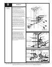
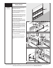
(JB-US) JAMB BRACKET INSTALLATION
Installing JB-US Jamb Brackets
4
(JB-US) Jamb
bracket
(1) 1/4” -
20 X 9/16”
Track bolt
(1) 1/4”- 20
Flange hex nut
Vertical
track