


20
Please Do Not Return This Product To The Store. Contact your local Wayne-Dalton dealer. To find your local Wayne-Dalton dealer, refer to your local
yellow pages business listings or go to the Find a Dealer section online at www.Wayne-Dalton.com
Tools Needed:
Tools Needed:
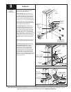
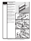
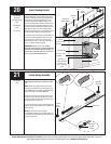
Center Bearing Bracket
Power Drill
7/16” Socket Driver
Level
Tape Measure
Pencil
1/4” Torx Bit
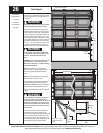
Measure to locate the center of the door and mark
a vertical pencil line on the mounting surface above
the door, to indicate the center line of the door. Then,
measure from the center of the bearing, in one of
the end bearing brackets, DOWN to the top of the
door. Using that dimension, measure UP from the top
of the door and mark a horizontal pencil line on the
mounting surface, intersecting the vertical pencil line.
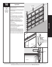
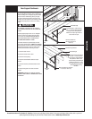
Now align the edge of the center bearing bracket
along the vertical pencil line on the mounting surface.
Center the bearing bracket on the horizontal line.
This will ensure the torsion tube is level between the
center and end bearing brackets. Attach the center
bearing bracket, in this location, to the mounting
surface, using (2) 5/16” x 1-5/8” lag screws and (1)
5/16” x 2” tamper-resistant lag screw.
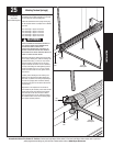
IMPORTANT: USE THE 5/16” X 1 5/8” TAMPER-
RESISTANT LAG SCREW ONLY IF MOUNTING SURFACE
MOUNTED OVER MASONRY. TAMPER-RESISTANT LAG
SCREW MUST BE ATTACHED THROUGH THE BOTTOM
HOLE OF THE CENTER BEARING BRACKET.
Vertical
line
Mounting
surface
Equal
distance
Center of end
bearing bracket
Horizontal
line
Center bearing bracket
Mounting
surface
Horizontal line
Center bearing
bracket
(1) 5/16” x 1-5/8”
Lag screw
(1) 5/16” x 1-5/8”
Lag screw
Vertical line
20
(1) 5/16” x 2”
Tamper-resistant
lag screw or (1)
5/16” x 1-5/8” lag
screw
21
none
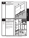
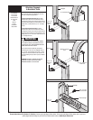
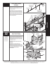
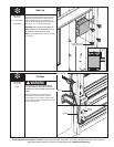
Torsion Spring Assembly
IMPORTANT: RIGHT AND LEFT HAND IS ALWAYS
DETERMINED FROM INSIDE THE BUILDING LOOKING
OUT.
NOTE: Identify the springs provided as either right
hand wound (red winding cone), which goes on the
LEFT HAND SIDE or left hand wound (black winding
cone), which goes on the RIGHT HAND SIDE.
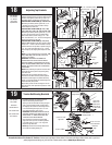
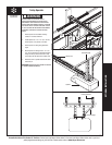
Facing the inside of the door, lay the torsion tube on
the floor. Lay the spring with the black color coded
winding cone and the black color coded cable drum,
at the right hand end of the tube.
Lay the spring with the red color coded winding cone
and the red color coded cable drum, at the left hand
end of the tube.
NOTE: The set screws used on all torsion
counterbalance winding cones and cable drums, are
now colored red. DO NOT identify right and left hand
by the set screw color.
Left hand
cable
drum red
RIGHT HAND WOUND RED
WINDING CONE LEFT HAND SIDE
Torsion tube
Right hand
cable drum
black
Nylon Center
bracket
bushing
LEFT HAND WOUND BLACK
WINDING CONE RIGHT HAND SIDE