


8 Freedom HF Installation Guide
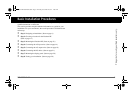
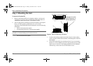
Basic Installation Procedures
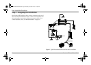
AC Distribution Panels
Most systems incorporate distribution centers both ahead of the Freedom
HF (the AC source panel) and between the Freedom HF and the loads (the
AC load panel). An AC source panel includes a main circuit breaker, which
serves as over-current protection and as a disconnect for the AC shore
power supply line. Additional circuit breakers serve individual circuits, one
of which serves the Freedom HF. The AC load panel can incorporate an AC
output circuit breaker and breakers for individual load circuits.
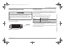
AC Cabling
AC cabling includes all the wires and connectors between the AC source
and the Freedom HF, as well as all cabling between the Freedom HF and
the AC output panels, circuit breakers, and loads. The type and size of the
wiring varies with the installation and load. For example, in high vibration
environments, such as marine or RV applications, wire nuts may not be
acceptable, so crimp splices would be required. In other applications,
flexible multiple-strand wire may be required. Installation codes usually
specify solid or stranded, overall size of the conductors, and type and
temperature rating of the insulation around the wire.
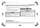
AC breakers and fuses must be sized to adequately protect the wiring that is
installed on the input and output AC circuits of the Freedom HF. All
breakers and wiring must be sized and connected in accordance with the
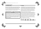
electrical codes or regulations applicable to your installation. Table 1 gives
some examples of wiring sizes based on the U.S. National Electrical Code
and the Canadian Electrical Code. These examples are based on using a 2-
conductor-plus-ground cable rated at 75 °C, and assuming an ambient
temperature of up to 30 °C. Ensure that your breakers, and fuses have
suitable temperature ratings for your wiring. Other codes and regulations
may also be applicable to your installation.
EQUIPMENT DAMAGE
Do not connect the output of the Freedom HF to what is known as a
“multi-wire branch circuit”. These are four-wire circuits consisting of a
ground, neutral, and two lines that are 180 degrees out of phase with each
other (from a standard 120/240V “split phase” circuit). These circuits are
commonly used in kitchens to power “split receptacles” where the top
and bottom halves of a duplex receptacle are connected to different lines.
Failure to follow these instructions can damage the unit and/or
damage other equipment.
Table 1
Required AC Wire Size vs Breaker Rating
Breaker Size (amps)
10A 15A 20A 30A
Minimum Wire Size
14AWG 14AWG 12AWG 10AWG
Freedom HF Install Guide.book Page 8 Thursday, November 24, 2011 11:06 AM