26 Freedom HF Installation Guide
Basic Installation Procedures
5. Remove the DC wiring cover to expose the ignition control terminals
of the DC wiring compartment.
6. Unscrew and remove the red jumper wire, using a flat screw driver, in
between terminal A and terminal Ignition Control. The jumper
wire acts to disable ignition control and removing it will enable it.
7. Strip the vehicle’s ignition control wire and connect it to terminal
Ignition Control.
NOTE: Do not make any external connections to terminal A. This can
result in non-warranty damage to the unit.
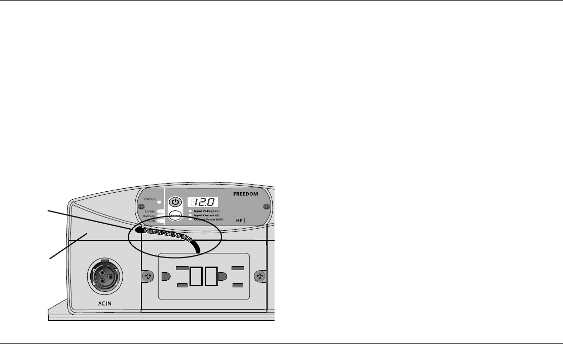
8. Route the ignition control wire to the left side of the display panel.
9. Replace the DC wiring cover onto the DC wiring compartment.
The ignition control wire should pass-through the hole on the side of
the DC wiring cover.
Power Module (For Freedom HF 1055 EMS and
1800 EMS)
In addition to having the ability to inhibit inverter operation in the absence
of a vehicle’s (or vessel's) ignition control signal, the Freedom HF 1055
EMS and 1800 EMS models also have the ability to provide auxiliary DC
power from the battery for small loads not exceeding 20 amps DC in total.
Auxiliary DC power is provided when the same ignition control signal is
present. This means that the vehicle’s ignition is turned to ON position. The
unit internally connects the DC OUT terminal to the battery’s positive
terminal.
To enable ignition control and to connect auxiliary DC power:
1. Ensure that AC and DC power are both OFF.
2. Ensure the vehicle’s ignition is turned to OFF position. It is highly
recommended to remove battery power by disconnecting the vehicle's
battery cables. Refer to the vehicle’s Owner’s Guide for proper
instructions on how to disconnect the battery cables.
3. Locate the vehicle's ignition control wire from the vehicle’s ignition
circuit. This must be fused appropriately at no more than five amps.
Refer to the vehicle’s Owner’s Guide for guidance.
4. Choose an auxiliary DC appliance that will be ignition controlled. The
appliance must be rated at 12-volts.
5. Unscrew and remove the red jumper wire, using a small flat screw
driver, in between the terminals Ignition Control and Disabled. The
jumper wire acts to disable ignition control and removing it will enable
it.
Ignition control
wire coming out
through hole.
DC wiring cover
Freedom HF Install Guide.book Page 26 Thursday, November 24, 2011 11:06 AM


