


34 Freedom HF Installation Guide
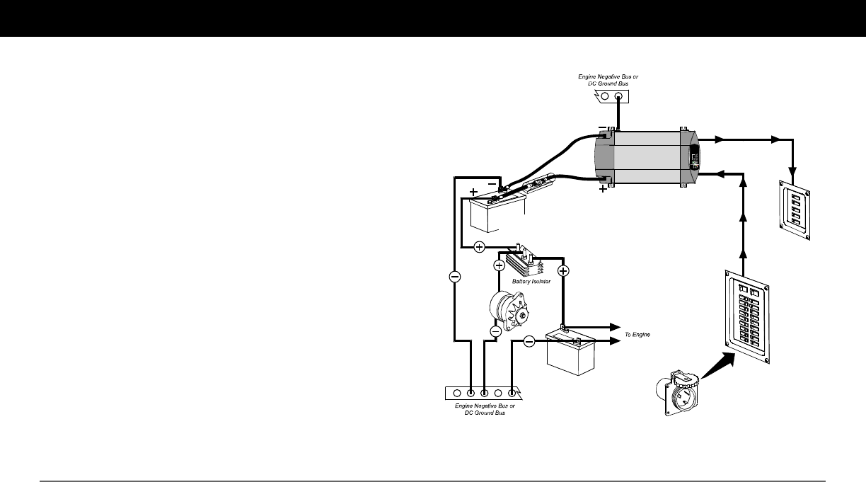
Marine Installation
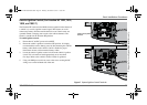
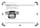
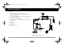
Figure 1 illustrates a typical marine installation with the following
components:
1. AC power supplied from a shore power connector
2. An AC source panel that includes a Max 30A circuit breaker that
supplies the Freedom HF
3. An AC load panel with branch circuit breakers that supply only loads
that run off the Freedom HF
4. Engine negative bus / DC ground bus
5. DC power supplied by a battery bank and protected by a DC fuse in
the positive cable
6. Battery isolator
7. DC alternator
8. Starting battery
9. Drip shield (not shown)
Figure 1
Typical Marine Installation
AC Load Panel
DC Fuse /
disconnect or
circuit breaker
AC Source Panel
12V Deep Cycle
Battery
Starting Battery
Shorepower
FR EED OM
HF| 1000
Freedom HF Install Guide.book Page 34 Thursday, November 24, 2011 11:06 AM