


975-0395-01-01 9
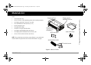
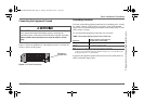
Basic Installation Procedures
This guide for use by qualified installers only.
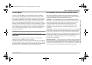
AC Output Neutral Bonding
The neutral conductor of the Freedom HF’s AC output circuit (i.e., AC
Output Neutral) is automatically connected to the safety ground during
inverter operation. When AC utility power is present and the Freedom HF is
charging, this connection is not present, so that the utility neutral (i.e., AC
Input Neutral) is only connected to utility ground at your source. This
conforms to National Electrical Code, which requires that separately
derived AC sources (such as inverters and generators) to have their neutral
conductors tied to ground in the same way that the neutral conductor from
the utility is tied to ground in only one place. Check the regulations for your
specific application to ensure that the installation will comply with the
necessary requirements. In other words, the AC Input Neutral and Output
Neutral must be isolated from each other.
AC Grounding
As per UL458 SA29.5, for all grounded AC cord-connected marine
inverter/chargers: The Freedom HF 1055 EMS and the Freedom HF 1800
EMS should be grounded to reduce risk of electric shock. Make sure that
the three-prong plug is plugged into properly installed and grounded AC
wall outlet in accordance with all local codes and ordinances.
As per UL458 SA29.5, for all permanently connected marine inverter/
chargers: The rest of the Freedom HF models should be connected to a
grounded, metal, permanent wiring system. Also, make sure that an AC
ground wire is connected to the AC ground terminal on the unit. Do not just
connect the line and neutral wires.
All connections to a unit should comply with all local codes and ordinances.
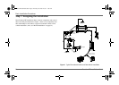
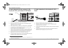
DC Cabling
This includes all the cables and connectors between the batteries, the DC
disconnect and over-current protection device, and the Freedom HF. Most
mobile installations require multi-strand insulated cables for flexibility and
durability in high vibration environments and require disconnects and over-
current devices. Electrical wiring sizes are indicated by AWG notation.
Under the AWG standard, a larger gauge number indicates a smaller wire
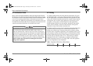
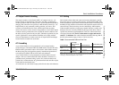
diameter. Wire size is usually marked on the larger sized cables. Table 2
specifies the minimum recommended DC cable size and maximum fuse
size for the Freedom HF. The DC cables must be copper and must be
rated 75 °C minimum. The cables should be terminated with lugs that fit
the DC stud terminals snugly (8 mm or 5/16 in. hole size).
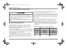
Table 2
Recommended Cable and Fuse Sizes
Inverter/Charger
Cable Length:
Battery to Inverter
(one way) Minimum Cable Size
Maximum battery Fuse
Size
Freedom HF 1000/
1055
Less than 5 feet
(1.5 meters)
No. 2 AWG 150 Adc
Freedom HF 1800 Less than 5 feet
(1.5 meters)
No. 2/0 AWG 250 Adc
Note: Xantrex recommends not using a cable longer than 5 feet (1.5 meters) in each direction.
Cable sizes above are based on the US National Electrical Code Table 310.17 - 75C cables,
assuming an ambient temperature of 30 °C cables.
Freedom HF Install Guide.book Page 9 Thursday, November 24, 2011 11:06 AM