


975-0395-01-01 27
Basic Installation Procedures
This guide for use by qualified installers only.
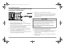
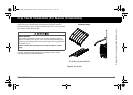
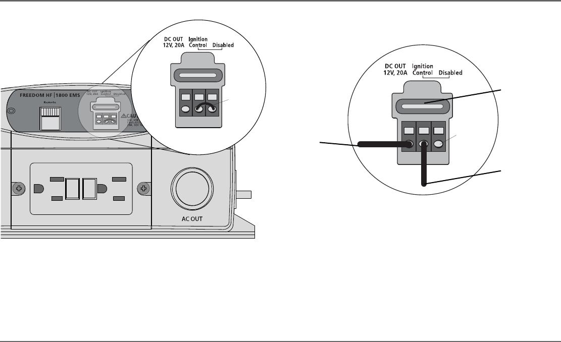
6. Strip the vehicle’s ignition control wire and connect it to the middle
terminal Ignition Control.
NOTE: Do not make any external connections to terminal Disabled.
This can result in non-warranty damage to the unit.
7. Locate wiring for the auxiliary DC appliance that will be ignition
controlled. Use a minimum of 10 AWG wire.
8. Strip the auxiliary DC wire and connect it to the left-most terminal
DC OUT 12V, 20A.
9. Connect the other end of the auxiliary DC wire to the DC appliance.
10. Reconnect the battery cables of the vehicle. Refer to the vehicle’s
Owner’s Guide for proper instructions on how to reconnect the battery
cables.
11. Turn the vehicle’s ignition to the ON position.
12. Turn the DC appliance on. Otherwise, if the DC appliance does not
have a switch it should automatically turn on at this point.
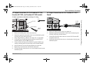
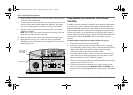
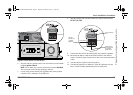
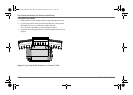
Figure 8
Power Module for EMS Models
RESET
TEST
TEST
RESET
FREEDOM HF 1800 EMS
JUMPER WIRE
DO NOT USE
Ignition Control Wire
Auxiliary DC Wire
Ignition control
wire connects to
the vehicle’s
ignition circuit.
This wire
connects to a
12-volt DC
appliance.
DC OUT 20-amp
fuse.
Freedom HF Install Guide.book Page 27 Thursday, November 24, 2011 11:06 AM