


22 Freedom HF Installation Guide
Basic Installation Procedures
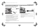
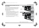
To make the DC connections
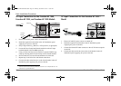
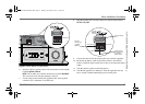
Refer to Figure 5.
1. Make sure the inverter is off and no AC or DC is connected to the unit.
2. Remove the nuts and washers from the Freedom HF positive and
negative DC terminals.
3. Strip 1/2 inch (13 mm) to 3/4 inch (19 mm) insulation from one end of
each cable. The amount stripped off will depend on the terminals
chosen.
4. Attach the connectors that will secure the cables to the battery, to the
disconnect/battery selector switch, and the fuse block. The connectors
you use must create a permanent, low-resistance connection.
If crimp connectors are required, Xantrex recommends using approved
and certified connectors, and to use the tool recommended by the
terminal manufacturer. Make sure no stray wires protrude from the
connector or terminal.
(You may find it more convenient to have the crimp connectors
attached by the company that sells you the cable and/or connectors.)
5. For each cable end that will be connected to the inverter, strip 1/2 inch
(13 mm) to 3/4 inch (19 mm) of insulation from the cable. The amount
stripped off will depend on the terminals chosen.
6. Thread a supplied DC terminal cover over the positive and negative
cables. The red cover goes on the positive cable; the black cover on the
negative cable.
7. Attach the connector that will join the cable to the inverter DC
terminal.
8. Install a fuse and fuse holder in the cable that will be used for the
positive side of the DC circuit.
The fuse must:
• be as close to the battery positive terminal as possible,
• be rated for DC circuits,
• have an Ampere Interrupting Capacity (AIC) that exceeds the
short-circuit current available from the battery (i.e., Class T fuse).
9. To prevent sparking when making the connection, ensure the
disconnect/battery selector switch is off.
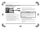
10. Attach the connector on the positive cable to the positive DC terminal
on the inverter.
11. Install the lock washer and nut that are supplied with the inverter.
Tighten the nut to a torque of 108–120 in-lbf (12.2–13.6 N-m). Make
the connection snug enough so the ring terminal does not move around
on the DC terminal, but do not overtighten. See Figure 5, “DC Cable
Connections” on page 23.
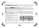
EQUIPMENT DAMAGE
Loose connections cause excessive voltage drop and may cause
overheated wires and melted insulation..
Do not over-tighten the nut on the DC input terminals. Damage to the DC
input terminals may result.
The maximum torque setting is 120 in-lbf (13.6 N-m).
Failure to follow these instructions can damage the unit and/or
damage other equipment.
Freedom HF Install Guide.book Page 22 Thursday, November 24, 2011 11:06 AM