


975-0395-01-01 13
Basic Installation Procedures
This guide for use by qualified installers only.
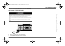
Connecting the Equipment Ground
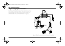
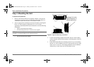
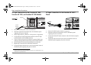
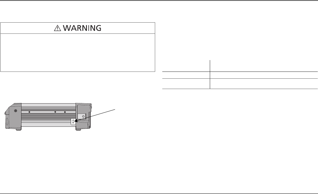
The Freedom HF has a ground stud on the side of the unit as shown in
Figure 3. Follow the guidelines in “Grounding Locations” to connect the
inverter’s chassis to the ground.
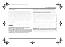
Grounding Locations
You must connect the equipment ground stud to a grounding point—usually
the vehicle’s chassis or DC negative bus ground—using recommended
copper wire (if insulated then green insulation with or without one or more
yellow stripes) or larger.
For recommended equipment ground cable size, see below.
In general, the equipment ground cable size must not be smaller than one
AWG size than the supply cable.
FIRE HAZARD
Never operate the Freedom HF without properly connecting the
equipment ground. A fire hazard could result from improper grounding.
Failure to follow these instructions can result in death or serious
injury.
Figure 3
DC Panel Connections
Equipment
ground stud
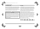
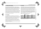
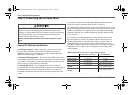
Table 3
Recommended Equipment Ground Cable size
Application
Minimum equipment ground cable size
(Stranded cable is recommended)
Recreational Vehicle
a
a. Based on US National Electrical Code NFPA70, Article 551, par. 551-20c 2005 version.
No. 8 AWG
Marine
b
b. Based on ABYC E-11 11.18 dated 07/03
No. 3 AWG (Freedom HF 1000)
No. 1/0 AWG (Freedom HF 1800)
NOTE: There are no restrictions on length for the equipment ground cable.
Freedom HF Install Guide.book Page 13 Thursday, November 24, 2011 11:06 AM