3.1 Examining
Figure 3-1
Hermes DXD
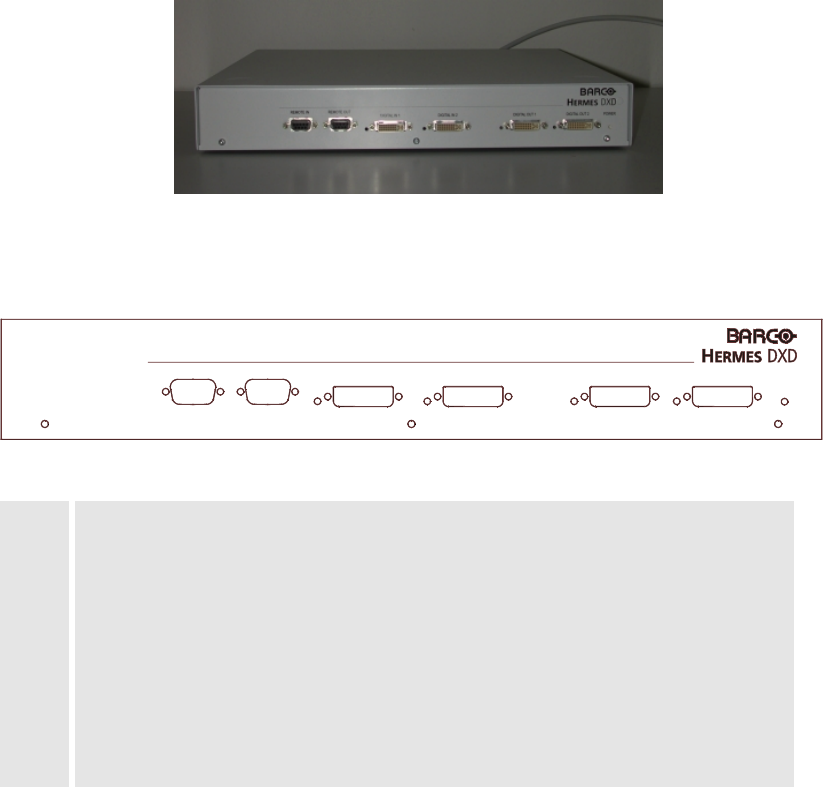
3.1.1 The Front Panel
The front panel of your HERMES DXD looks like this or similar:
1
POWERDIGITAL OUT 2DIGITAL OUT 1DIGITAL IN 2DIGITAL IN 1REMOTE OUTREMOTE IN
234 56 78 910 11
Figure 3-2
Front Panel of Hermes DXD
1 REMOTE IN
2 REMOTE OUT
3 LED: DIGITAL IN 1
4 DIGITAL IN 1
5 LED: DIGITAL IN 2
6 DIGITAL IN 2
7 LED: DIGITAL OUT 1
8 DIGITAL OUT 1
9 LED: DIGITAL OUT 2
10 DIGITAL OUT 2
11 LED: POWER
The REMOTE IN socket [1] is for plugging in the remote control cable coming from the previous device
(or the controlling PC), the
REMOTE OUT [2] for the cable leading to the next device.
The
DIGITAL IN 1 socket [4] is for connecting HERMES DXD with the graphic card of a graphical con-
troller. The DVI cable is plugged in here. If a signal is applied to
DIGITAL IN 1, the LED [3] is green,
else off.
The
DIGITAL IN 2 socket [6] is for connecting HERMES DXD with the graphic card of a graphical con-
troller. The DVI cable is plugged in here. If a signal is applied to
DIGITAL IN 2, the LED [5] is orange,
else off.
The
DIGITAL OUT 1 socket [8] is for connecting HERMES DXD with the projection unit of a Barco pro-
jection cube. If the signal of
DIGITAL IN 1 is applied to DIGITAL OUT 1, the LED [7] is green, if the sig-
nal of
DIGITAL IN 2 is applied to DIGITAL OUT 1, the LED [7] is orange.
The
DIGITAL OUT 2 socket [10] is for connecting HERMES DXD with the projection unit of a Barco
projection cube. If the signal of
DIGITAL IN 1 is applied to DIGITAL OUT 2, the LED [9] is green, if the
signal of
DIGITAL IN 2 is applied to DIGITAL OUT 2, the LED [9] is orange.
The LED POWER [11] indicates the device is switched on and operating properly. If the LED is off,
H
ERMES DXD is switched off or the internal logic control has detected an error.


