


4.1 Cabling
A remote control system consists of three different components:
remote control master (
RCM)
remote control slave (
RCS)
remote control connection
The
RCM is the central computer which controls the slave devices RCS. All control messages are gener-
ated by the
RCM, addressed to a certain RCS device and sent on. Incorrect messages are processed by a
RCS and directed to the RCM without request.
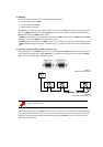
All
RCS are connected in series. Messages sent from the RCM are passed on by an RCS to the next RCS,
and finally return to the
RCM. The messages run in a ring.
The RCM must be connected to each RCS in series. For a clear lay-out of the cabling the different types
of
RCS should be arranged into blocks within the ring, e. g. all HERMES DXD first, then all illumination
units.
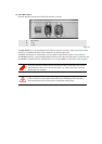
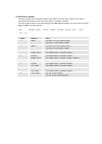
4.1.1 Cabling of Hermes DXD (number of devices < 20)
The serial interface of the RCM (COM1) must be connected to the Remote In socket of the first HERMES
DXD. Each following HERMES DXD (Remote In) is connected to the previous HERMES DXD (Remote
Out
). This kind of connection is called daisy chain.
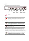
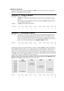
Figure 4-1
Remote Control Interfaces
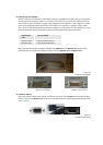
Figure 4-2
Daisy chain cabling of devices
A shorting plug must be inserted into the REMOTE OUT socket of the last device in
order to close the ring.
If the internal logic control of a RCS detects an error, or if a device is switched off, the input and output
of its remote control interface are short-circuited, such that all other remote control devices can still be
addressed. Pay attention that during the addressing procedure all
RCS are active, in order to prevent
confusion in the addresses