3.1.2 The Back Panel
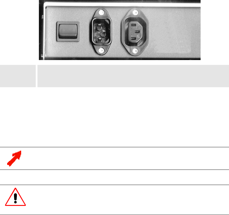
The back panel of your HERMES DXD looks like this or similar:
A
BC
A Main Switch
B AC In
C AC Out
Figure 3-3
The Main Switch [A] is for switching HERMES DXD on and off. If the 0 is visible on top of the switch,
the device is switched off, and it can be switched on by pressing the switch.
The
AC In socket [B] is for connecting to a power supply as specified in section 7.1.2 Power Supply.
The AC Out socket [C] is for connecting further devices (of type HERMES DXD only!) to the power sup-
ply.
AC Out is connected directly to AC In and is live as soon as AC In is connected to a power supply.
Up to max. ten HERMES DXD devices can be put on top of each other. Thus you can
group the devices into towers next to each other, e. g., in the same order as the pro-
jection cubes are arranged.
To protect HERMES DXD from overheating, the air supply openings in the case must
not be covered! If you group the devices into towers standing next to each other a
space between the devices not less than 10 centimeter must be kept!


