


D9112 Operation & Installation Manual
Page 29
© 1993 Radionics
74-06144-000-C 2/96
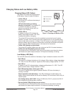
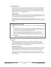
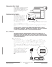
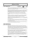
Phone Line Test Points
You can attach a telephone test set to
the D9112 at the TELTEST points
located above the TELCO jack on the
lower left corner of the panel. See
Figure 7.
Communication Failure
After 10 attempts to reach the
receiver, the panel goes into
communication failure. The
panel clears any reports in its
phone buffer. SERVC COMM
FAIL appears in the display at
command centers.
If you use the D128 Dual Phone Line
Switcher, the D9112 makes 10 attempts on each line before going into communication
failure.
Pressing Command 4 silences the tone. When communication restores (a report is
acknowledged by the receiver), the display clears automatically. See
Phone Parameters
in the
D9112 Program Entry Guide
(74-06145-000) for reporting options
.
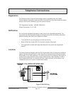
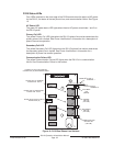
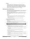
Ground Start
Some telephone systems require a momentary ground input to initiate dial tone. To
interface with a ground start system, insert a plug-in relay (D136) into socket K6/J5 and
set the ground start jumper in the GND START position. Terminal 10 must be connected
to an earth ground reference.
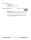
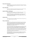
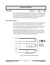
Relay Installation
Power down the D9112 before inserting the D136 relay into socket K6/J5. The relay
socket is in the lower left corner as shown in Figure 8. The plug-in relay is shorter than
the socket it plugs into. You can install it in either the left or right end of the socket.
Don’t rely on relay labeling:
You shouldn’t rely on the labelling to install D136
relays. Check for the side with three pins. The three pins go on the top
side.
Incorrect insertion does not damage the
relay or the D9112, however the
related circuits do not function
properly. A ground start relay must
not be inserted when dialing loop
start.
EARTH GROUND
COMMON
LINE SNIFFER SELECT
Loop Start
Ground Start
TELCO CORD
MODEL No. D161
PHONE
LED
ON WHEN
COMMUNICATING
OFF WHEN IDLE
Requires
Optional Relay
Model No. D136
Operation Monitor
Pulses When Normal
Flickers When Ringing
Solid When Held In Reset
32
31
30
+
25
27
28
RED
GROUND
START
YEL
RED
RADIONICS D9112
23
29
26
Reset Pin
Disable All Except Battery
Charging And Local Programming
GRN
+
+
+
24
Also Suitable for Supplementary and Supervisory Electrically Actuated Transmitter Use
ALL TERMINALS EXCEPT #5 (BATTERY POSITIVE) POWER LIMITED
See 73-06143-000 for Compatible Smoke Detectors
12 15 18 211311 14 16 17 19 20 22
3
5
6
7
8
9
10
1
4
2
M
OPERATION
MONITOR LED
(GREEN)
PHONE LINE
MONITOR SELECT
JUMPER
PHONE LINE
TEST POINTS
TELCO CORD
CONNECTOR (J3)
GROUND START
RELAY (J5)
PHONE LED
(RED)
M
Figure 7: Telephone Connections
Figure 8: Ground Start Relay
M
Aromat
DS2E-M-DC12V
GROUND START RELAY