


D9112 Operation & Installation Manual
Page 34
74-06144-000-C 2/96
© 1993-1996 Radionics
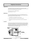
Point Parameters
You can determine the condition of on-board points 1 to 8 by measuring the voltage
across the point input terminal and one of the common terminals. The sensor loops must
be connected and the 1k ý end of line resistor in place.
Open Loop = Greater than 3.7 VDC, but less than 5.0 VDC.
Normal Loop = Greater than 2.0 VDC, but less than 3.0 VDC.
Shorted Loop = Greater than 0.0 VDC, but less than 1.3 VDC.
Point Response Time
The D9112 Control/Communicator scans both on-board and off-board point sensor loops
every 300 milliseconds. The
Debounce Count
program item in the
Point Assignment
module determines point response time by setting the number of scans that a point must
be faulted before the panel initiates an alarm.
The debounce count can range from 1 to 15. Therefore point response time ranges from
300 milliseconds to 4.5 seconds. The Radionics default for Debounce Count is 2.
Warning, increasing debounce count may cause missed alarms:
If you increase the
Debounce Count, detection devices may go into alarm and reset without exceeding the
point response time.
Radionics recommends you leave the debounce count at 2 for all points.