


D9112 Operation & Installation Manual
Page 33
© 1993 Radionics
74-06144-000-C 2/96
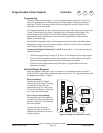
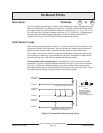
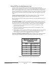
On-Board Points
Description Terminals 11 to 22
The D9112 panel provides eight on-board points. Each point functions independently and
does not interfere with the operation of the others. The panel monitors the sensor loops
for normal, shorted, or open conditions between an input terminal (11, 13, 14, 16, 17, 19,
20, or 22) and any of the point common terminals (12, 15, 18, and 21). Programming for
the point determines how the panel responds to those conditions. See the
D9112
Program Entry Guide (74-06145-000)
for point programming options.
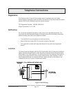
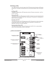
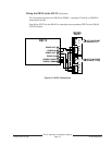
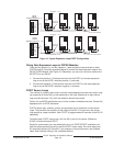
Point Sensor Loops
When wiring the on-board points, install a 1k ý resistor at the far end of the sensor loop
to provide a reference for supervision. You can connect dry contact sensing devices in
series (normally-closed) and/or in parallel (normally-open) to any of these loops.
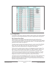
The number normally-open and/or normally-closed detection devices each sensor loop
can supervise is limited only by the resistance on the loop. Resistance on each sensor
loop must be less than 100ý with the detection devices connected.
Ground shunts cause missed alarms:
The possibility of “ground shunts” increases
significantly if you don’t install the resistor at the end of the line. If you install the resistor
for points 1 to 8 before a detection device on the sensor loop and the loop becomes
grounded after the resistor, any devices beyond the ground are “ground shunted”. Alarm
or trouble conditions beyond the ground are not seen by the panel.
POINT INPUT
TERMINAL
COMMON
POINT INPUT
TERMINAL
COMMON
COMMON
NORMALLY OPEN CONTACTS
COMBINATION: NORMALLY OPEN AND
NORMALLY CLOSED CONTACTS
RADIONICS MODEL
D105F OR D105BL (UL
LISTED BURGLAR
APPLICATIONS)
END-OF-LINE RESISTOR
BROWN
BLACK
RED
1K Ω
NORMALLY CLOSED CONTACTS
POINT INPUT
TERMINAL
Figure 11: On-board Point Sensor Loop Wiring