


D9112 Operation & Installation Manual
Page 51
© 1993-1996 Radionics74-06144-000-C 2/96
D811 Arm Status Relay Module
The 811 Arm Status Relay Module allows you to add a single off-board relay output to
your system. When used with the D9112 you can assign alarm output, auxiliary relay,
sensor reset, arming status, point status, alarm memory, or remote functions (Command
54) to the D811 relay output. You are not restricted to the arming status mode only.
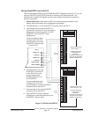
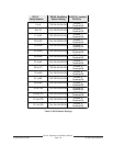
Relay numbers for D811 not programmable:
If you connect the D811 to ZONEX 1,
terminal 28 on the D9112, you must use relay number 53 for the relay output. If you
connect the D811 to ZONEX 2, terminal 26 on the D9112, you must use relay number
117 for the relay output.
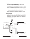
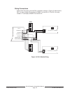
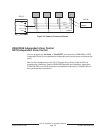
D811 modules connect as shown in Figure 18. Review the
Power Outputs
section of this
manual to be sure you provide enough power for the powered devices you wish to
connect to your system. See
Relay Parameters
in the
D9112 Program Entry Guide
(74-
06145-000)
for programming details.
D811 restricted for fire systems:
The D811 relay output is not supervised and can not
be used in fire or combined fire/burglary installations for primary indication devices.
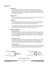
Relay Output
Each D811 relay output provides a Form C dry contact rated for 1.0A at 12 VDC.
Normally-open, common, and normally-closed terminals are available. When an
individual output is activated, there is continuity between the normally-open and common
terminals. When the output is not activated, there is continuity between the normally-
closed and common terminals.
Warning:
Relay outputs may activate while programming the panel. You may wish to
disconnect equipment connected to relay outputs while performing these functions.
Installation
Do not use the instructions packaged with the D811:
The literature packaged with
the D811 module is not for use with the D9112 panel. Use the instructions below.
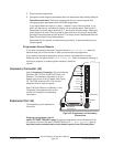
You can install the D811 in the enclosure with the D9112 (see Figure 2) or in an adjacent
enclosure not more than 5 feet from the D9112. Use 16 to 22 AWG wire.
Follow the procedure below to install D811 modules in the enclosure with the D9112.
1. Align the D811 module with any of the four mounting locations in the enclosure. See
Figure 2.
2. Use the screws provided with the module to secure it in the enclosure.
Use the D137 Mounting Bracket to install D811 modules in enclosures with no module
mounting locations available.