


D9112 Operation & Installation Manual
Page 45
© 1993-1996 Radionics74-06144-000-C 2/96
OctoPOPIT Sensor Loops
The number normally-open and/or normally-closed detection devices each sensor loop
can supervise is limited only by the resistance on the loop. Resistance on each sensor
loop must be less than 100ý with the detection devices connected.
Certain UL and NFPA applications may limit the number of detection devices. Consult the
appropriate UL or NFPA standards.
The OctoPOPIT detects open, short, closed, normal, and grounded circuit conditions on
its sensor loops and transmits the conditions to the D9112. A ground on the positive leg
of the sensor loop transmits a shorted condition for the point. Each sensor loop is
assigned a point number and transmits to the D9112 separately. See
Point Assignment
Switches
below.
Radionics recommends you use twisted-pair wire for the OctoPOPIT sensor loops to
avoid EMI problems. Run wires away from the premises telephone and AC wiring. If you
suspect a noisy environment, use shielded cable. See
EMI on Long Wire Runs
in the
Troubleshooting
section.
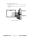
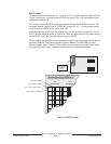
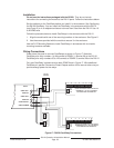
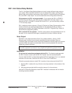
There are two rows of terminal numbers on the D8128A. See Figure 16. In the row
closest to the terminal blocks, the positive outputs for the sensor loops are labeled
P1
to
P8
. Sensor loop outputs P1 and P2, P3 and P4, P5 and P6, and P7 and P8 share
common terminals. The common terminals for each pair are labelled
COM.
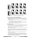
Sensor Loop Switches
Switches 1 to 8 activate each of the eight OctoPOPIT sensor loops. Setting the switch
ON enables reports from that sensor loop. Setting the switch to OFF disables the loop. If
you disable a sensor loop assigned to a point that the D9112 expects to see, the D9112
interprets it as a missing point.
Always set the Sensor Loop switch for points 72 and 136 to OFF:
The D9112
reserves points 72 and 136 for internal functions. Set switch P8 to OFF to disable the
sensor loop for those points. Setting P8 to ON for points 72 and 136 may cause
erroneous PT BUS TROUBLE reports.
Switch 1 corresponds to sensor loop 1 (terminal P1), switch 2 corresponds to sensor loop
2 (terminal P2), and so on.
Terminate each OctoPOPIT sensor loop with a 1k ý end-of-line resistor. Attach a resistor
even if you don’t enable the loop. The OctoPOPIT comes with a Radionics D105BL
resistor for each sensor loop.
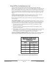
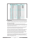
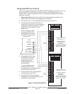
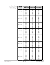
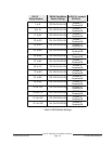
Point Assignment Switches
Switches 9, 10 and 11 on the OctoPOPIT assign the sensor loops to D9112 point
numbers. Table 2 shows the OctoPOPIT switch settings for point assignments. Each
setting assigns point numbers to all eight sensor loops. Set the sensor loop switches (1 to
8) to OFF for points on the OctoPOPIT you don’t intend to use.
Duplicated points do not function correctly:
Take care not to duplicate point
assignments. Points assigned to both an OctoPOPIT sensor loop and a POPIT, two
OctoPOPIT sensor loops, or two POPITs, do not function properly.
NCI
#215