


D9112 Operation & Installation Manual
Page 62
74-06144-000-C 2/96
© 1993-1996 Radionics
Introduction
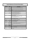
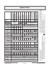
The
D9112 System Chart
references components evaluated and listed by Underwriters’
Laboratories for compatibility with the D9112 Control/Communicator. These components
meet the basic system requirements for the applicable standard.
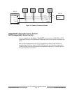
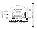
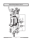
The
System Wiring Diagram, Issue A
shows the relationship between the D9112 panel and
the accessory components referred to in the
D9112 System Chart.
Optional Compatible Equipment
You can use UL listed components that do not require evaluation for electrical compatibility
in many applications when installed according to the manufacturer’s instructions.
Burglary Applications
You can use UL listed burglary alarm sensors that do not require evaluation for electrical
compatibility in burglary applications. In some cases you must use a UL listed Radionics
interface module in conjunction with the sensors. Consult the individual component
specification and installation documents to determine suitability.
Test weekly:
UL Standard 1023 requires a weekly test for residential burglary
applications.
Fire Applications
You can use UL listed fire initiating devices not requiring electrical compatibility
evaluation in any application. For example: 4-wire smoke detectors, heat detectors, water
flow switches, and manual pull stations are suitable fire initiating devices. Consult the
individual component specification and installation documents to determine suitability.
Two-wire smoke detectors only connect to the D9112 through the D125B Powered Loop
Interface so that an earth ground will not cause an alarm. Two-wire detectors must be
evaluated for electrical compatibility, and must be UL listed for use with the D9112. See
the Radionics Technogram
Smoke Detectors Compatible with the D9112
(73-06143-
000), or you may contact the detector manufacturer.
Other initiating devices, including four-wire smoke detectors connect to the D9112
through the D129 Dual Class A Initiation Circuit Module, the D125B Powered Loop
Interface, or D8127 POPITs. When using 4-wire smoke detectors, install a suitable power
supervision unit according to the manufacturer’s instructions. Use the D130 Relay
Module, D8129 OctoRelay, or terminal 8, Switched Aux Power to provide reset capability.
See the
Off-Board Relays
section of this manual for details on installation of the D8129.
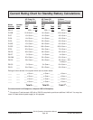
For battery calculations, refer to pages 68-69 and the current rating chart on page 66.
Test weekly:
Radionics recommends you perform a Fire Test (Command 58) weekly.
The AC power is automatically tested as is the battery per UL 864.