


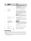
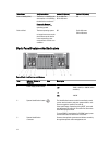
Item Indicator, Button, or
Connector
Icon Description
Press to toggle the system ID on and off.
If the system stops responding during POST, press and
hold the system ID button for more than five seconds to
enter BIOS progress mode.
To reset iDRAC (if not disabled in F2 iDRAC setup), press
and hold the button for more than 15 seconds.
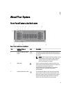
4 Video connector Allows you to connect a VGA display to the system.
5 LCD menu buttons Allows you to navigate the control panel LCD menu.
6 LCD panel Displays system ID, status information, and system error
messages. The LCD lights blue during normal system
operation. The LCD lights amber when the system needs
attention, and the LCD panel displays an error code
followed by descriptive text.
NOTE: If the system is connected to a power source
and an error is detected, the LCD lights amber
regardless of whether the system is turned on or off.
7 USB connectors (2) Allows you to connect USB devices to the system. The
ports are USB 2.0-compliant.
8 Enterprise Service Tag A slide-out label panel, which allows you to record system
information such as Service Tag, NIC, MAC address, and
so on, as per your need.
9 Hard drives (number of
drives will be either 4 or 24
depending on the backplane
configurations)
2.5 inch hard drives
NOTE: On the backplane supported Flash devices,
there are 3 bays in total. The first two bays are for
PCIe Flash devices with two sets of drives labelled 0
through 3. The bay 3 is for SAS drives labelled 0
through 15.
10 Slide lock A lock that pops out the ejector handle for the optical
drive.
11 Optical drive (optional) One optional SATA DVD-ROM drive or DVD+/- RW drive.
12 Rack ears Allows you to pull the system out of the rack.
13 vFlash media card slot Allows you to insert a vFlash media card.
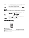
LCD Panel Features
The system's LCD panel provides system information and status and error messages to indicate when the system is
operating correctly or when the system needs attention. See System Error Messages for information about specific
error codes.
• The LCD backlight lights blue during normal operating conditions and lights amber to indicate an error condition.
• The LCD backlight is off when the system is in standby mode and can be turned on by pressing either the Select,
Left, or Right button on the LCD panel.
10