


Installing The RAID Battery
CAUTION: Many repairs may only be done by a certified service technician. You should only perform
troubleshooting and simple repairs as authorized in your product documentation, or as directed by the online or
telephone service and support team. Damage due to servicing that is not authorized by Dell is not covered by your
warranty. Read and follow the safety instructions that came with the product.
1. Turn off the system, including any attached peripherals, and disconnect the system from the electrical outlet.
2. Open the system.
3. Remove the storage controller card.
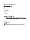
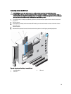
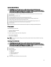
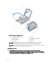
4. Connect the RAID battery cable connector on the storage controller card.
5. Align the RAID battery module (battery and carrier) with the slots on the storage controller card.
6. Push the battery module into the slots, so that it snaps in place.
7. Connect the SAS data cables to the data cable connectors on the integrated storage controller card.
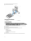
8. Insert the storage controller card into the connector on system board.
9. Close the system.
10. Reconnect the system to its electrical outlet and turn the system on, including any attached peripherals.
Processors
Use the following procedure when:
• Installing an additional processor
• Replacing a processor
Your system supports two types of processor configurations:
• Four-processor configuration
• Two-processor configuration
NOTE: To ensure proper system cooling, you must install a processor blank and a heat-sink blank in any empty
processor socket.
Removing A Heat Sink Blank
CAUTION: Many repairs may only be done by a certified service technician. You should only perform
troubleshooting and simple repairs as authorized in your product documentation, or as directed by the online or
telephone service and support team. Damage due to servicing that is not authorized by Dell is not covered by your
warranty. Read and follow the safety instructions that came with the product.
1. Turn off the system, including any attached peripherals, and disconnect the system from the electrical outlet.
2. Open the system.
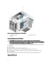
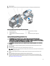
3. Remove the following:
a. memory risers
b. cooling fans
c. memory riser and fan cage
d. cable management tray
e. fan tray
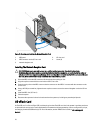
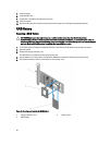
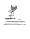
4. Locate the heat sink blank seated on the processor blank.
83