


1-7
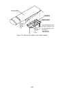
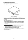
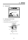
1.2.2 Mounting the processor unit
1. Drill four holes of 12 mm in diameter in the mounting location.
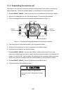
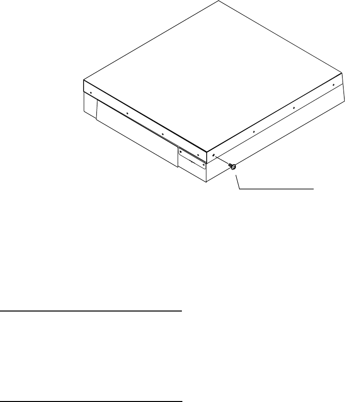
2. Unfasten 15 binding screws (M4) to remove the processor unit cover.
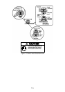
WARNING
Binding Screw
M4X8, 15 pcs.
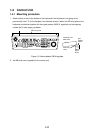
Figure 1-5 Processor unit
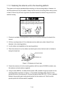
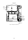
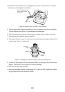
3. Fasten the processor unit to the mounting location with four each of M10 bolts, nuts and
washers, using the pipe box spanner (supplied). See the figure on the next page for location
of fixing holes.
How to access the rear-left fixing hole
The rear-left fixing hole is hidden under the PTU board cover. To access it do the following:
a) Loosen five M3X8 screws at the top of the PTU board cover and two M4X8 screws at the
front of the cover.
b) Grasp the knob on the cover and slide the cover toward the front of the unit to release it.
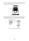
How to access the front-right fixing hole
The front-right fixing hole is hidden beneath the RGB Board. To access it do the following:
a) Unfasten the M4X8 pan-head screw from the RGB board mounting plate.
b) Unfasten two pan-head screws (M3X10) fixing the M-card cover.
4. After mounting the unit, fasten the PTU board cover and RGB board mounting plate, and
then close the processor unit.