


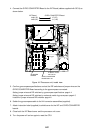
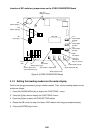
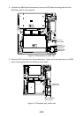
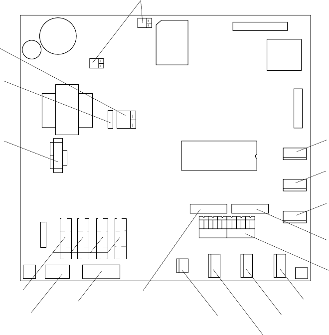
4-6
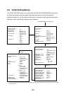
Location of DIP switches, jumper wires on the GYRO CONVERTER Board
64P1106
JP5, JP4
(Supply voltage)
JP2
(Rotor voltage)
JP3
(Stator voltage)
JP1
(Gyro type)
Fuse
(2A)
J5
(Rotor signal input,
external power input)
J4
(Stator signal input)
SW1
DIP switch
J6
(IEC-61162-1 output port)
J7
(Data output port #1)
J8
(Data output port #2)
J9
(Data output port #3)
JP6, JP7
(AD formal
data Tx interval)
SW2
DIP switch
J10
(Data output
port #4)
J11
(Data output
port #5)
J12
(Data output
port #6)
Figure 4-4 GYRO CONVERTER Board
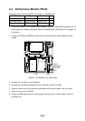
4.1.3 Setting the heading readout on the radar display
Confirm that the gyrocompass is giving a reliable readout. Then, set the heading readout on the
monitor as follows:
1. Press the [RADAR MENU] key to display the FUNCTIONS 1 menu.
2. Press the [0] key twice to display the FUNCTIONS 3 menu.
3. Press the [9] key to select the GYRO SETTING option.
4. Rotate the EBL control to align the radar's HDG readout with the gyrocompass heading.
5. Press the [ENTER] key to finish.