


4-12
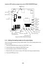
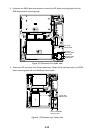
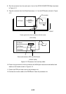
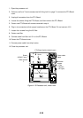
8. Run the connector from the card case in front of the GYRO CONVERTER Board as shown
in Figure 4-12.
9. Plug the connector from the M-card base assy. in J1 on the RP Board as shown in Figure
4-12.
INT Board
GYRO
CONVERTER
Board
FRONT
Fasten ground wire from connector with this screw.
RP connector
(TOP VIEW)
(FRONT VIEW)
RP Board
ARP Board
SPU Board
Route cable between ARP and SPU Boards.
J1
Figure 4-12 Processor, front and top views
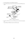
10. Fasten the ground wire from the connector with M3X8 pan-head screw and teethed lock
washer at the location shown in Figure 4-12.
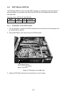
11. Fasten the PCB card case cover to the processor unit.
12. Connect the monitor cable to the RGB Board. Close the processor unit.