


4-1
1. OPTIONAL EQUIPMENT
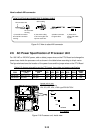
4.1 Gyro Converter GC-8
The Gyro Converter GC-8, incorporated inside the processor unit, converts analog
gyrocompass reading into digital coded bearing data for display on the monitor.
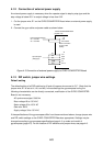
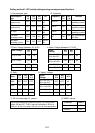
This section explains how to install and the GC-8 (mainly consisting of the GYRO CONVERTER
Board) and set it up according to the gyrocompass connected.
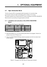
4.1.1 Installation and connection of the GYRO CONVERTER
Board
Necessary Parts: GC-8 (Code No. 008-446-520)
Name Type Qty Code No.
Gyro Converter Board 64P1106 1 004-412-226
Washer-head Screw M3X8, C2700W 5 000-881-404
Sticker 64-014-20211 1 100-132-701
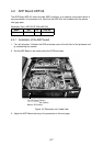
1. Turn off the main POWER switch.
2. Open the processor unit. Turn off the internal power switch if so equipped. Unfasten four
screws to remove the INT Board cover.
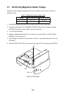
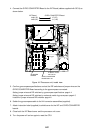
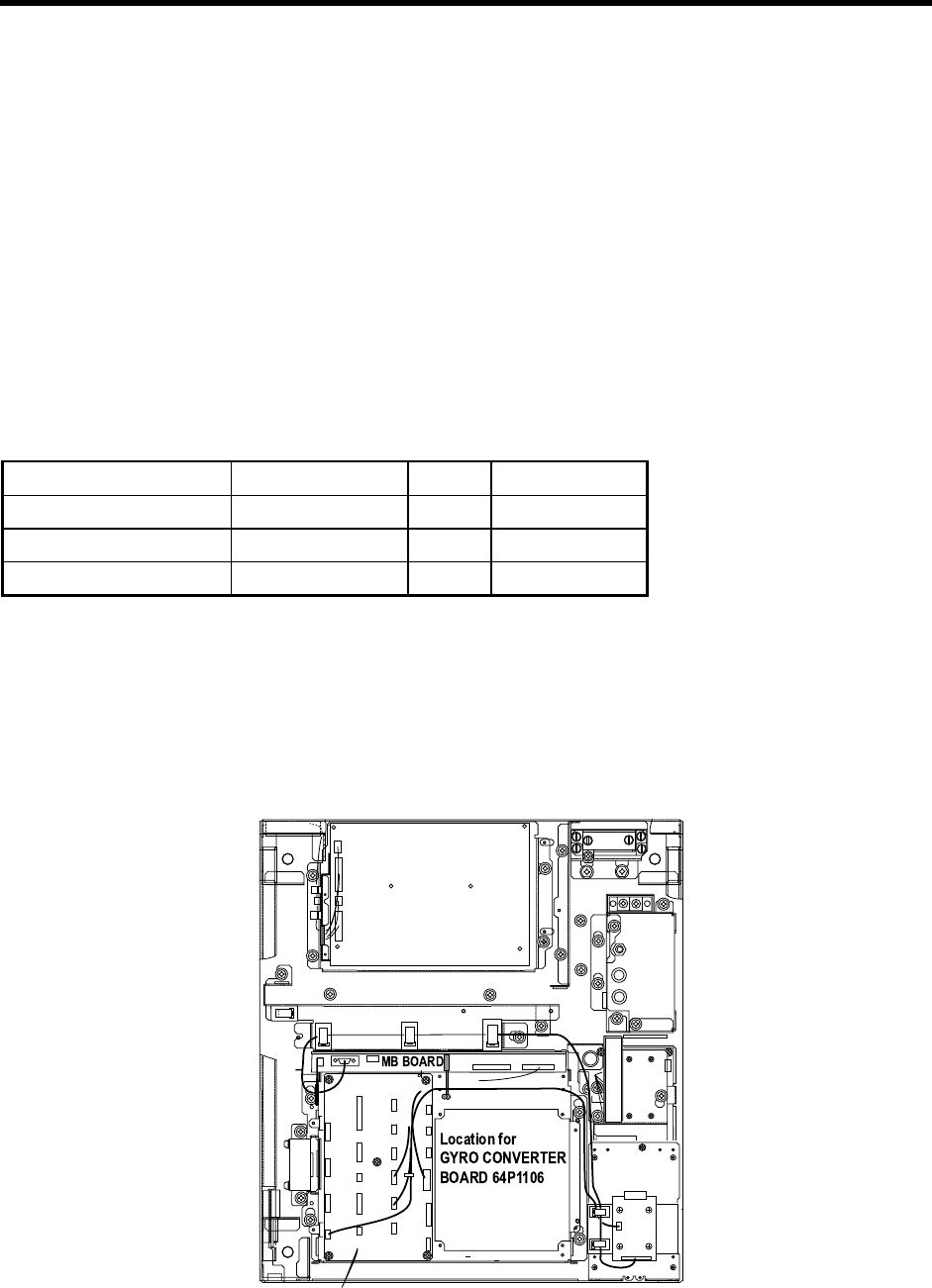
3. Fasten the GYRO CONVERTER Board inside the processor unit with four washer-head
screws (supplied).
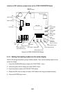
PTU BOARD
03P9245A - F
INT BOARD 03P9252
Figure 4-1 Processor unit, inside view, INT board cover removed