


4-9
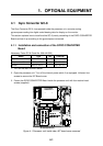
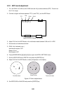
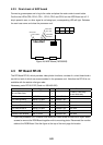
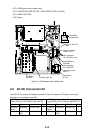
4.2.3 Final check of ARP board
Connect a gyrocompass and a log to the radar and place the radar under transmit state.
Confirm that LEDs CR9, CR10, CR11, CR12, CR15 and CR16 on the ARP Board are off. If
ship's speed is zero, or other signal is not being input, corresponding LED will light. Refasten
the card case cover and close the processor unit.
S1
CR16 LOG
CR15 GYRO
CR9 HDG
CR10 BRG
CR11 VID
CR12 TRG
4#3#2#1#
FFOFFOFFOFFO
Figure 4-8 ARP Board (18P9002B)
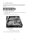
4.3 RP Board RP-26
The RP Board RP-26, which provides video plotter functions, consists of a circuit board and a
card drive, both of which are accommodated in the processor unit. Note that the RP-26 is not
available with the statute mile-type radar.
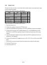
Necessary parts: RP-26-Z-2E (Code no. 008-485-520)
Name Type Qty Code No. Remarks
M-card Base Assy.
−
1
IF Board, Cable assy.,
M-card base assy.
RP Board 14P0298 1 008-487-640
Pan-head Screw B M4X8 C2700W 4 000-881-445
Pan-head Screw B M3X8 C2700W 2 000-881-404 Not used
Pan-head Screw A M2.6X5 C2700W 2 000-800-973 Not used
Pan-head Screw A M3X8 C2700W 1 000-881-104 Not used
Teethed Lock Washer M4 C5191W 1 000-864-506
Teethed Lock Washer M4 C5191W 1 000-864-504 Not used
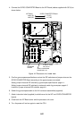
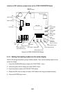
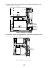
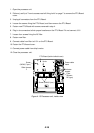
1. Open the processor unit. Unfasten one M4X8 pan-head screw and two M3X10 pan-head
screws to remove the RGB Board together with its mounting plate. Disconnect the monitor
cable at the RGB Board. See the figure at the top of the next page for location.