


4-14
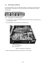
4.5 Alarm Kit
The alarm kit mainly consists of a circuit board and connection cables, and provides alarm output
to ship's bridge alarm system.
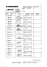
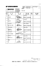
Necessary parts: OP03-156 (Code no. 008-500-650)
Name Type Code No. Qty
ALARM Board 03P9262 008-500-680 1
NH Connector Assy. 03-1990(9-9P) 008-500-700 1
NH Connector Assy. 03-1991(3P) 008-500-710 4
Cable Band HP-3N 000-570-001 1
Cable Tie CV-100 000-570-322 3
Pan-head Screw B M3X8 C2700W 000-881-404 4
Pan-Head Screw B M3X8 C2700W 000-881-447 1
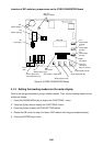
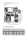
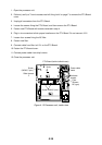
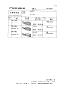
Refer to the figure on the next page for parts location.
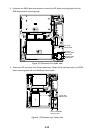
1. Open the processor unit.
2. Unfasten four screws to dismount the INT Board cover.
3. Fasten the ALARM Board to the processor unit with four M3X8 pan-head screws (supplied).
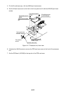
4. Connect the NH connector (9-9P, supplied) between J471 on the ALARM Board and J451
(EXT-BUZ) on the INT Board, passing it through the cable band and binding it with existing
cable tie.
5. Fasten the cable band (supplied) with a pan-head screw (M4X12, supplied) and attach two
cable ties (CV-100, supplied).
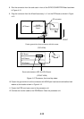
6. Connect a NH connector (3P, supplied) to each of J472, J473, J474 and J475 on the ALARM
Board.
7. Route the NH connectors along the cable ties and pass them through the cable clamp.
8. Close the INT board cover.
9. Close the processor unit.