


4-16
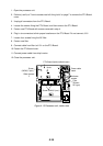
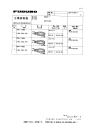
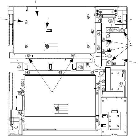
1. Open the processor unit.
2. Follow a) and b) of "how to access rear-left fixing hole" on page 7 to remove the PTU Board
cover.
3. Unplug all connectors from the PTU Board.
4. Loosen the screws fixing the PTU Board, and then remove the PTU Board.
5. Fasten new PTU Board with screws removed in step 4.
6. Plug in six connectors to their proper locations on the PTU Board. Do not connect J101.
7. Loosen four screws fixing the AC filter.
8. Fasten new filter.
9. Connect cable from filter to J101 on the PTU Board.
10. Fasten the PTU board cover.
11. Connect power cable from ship's mains.
12. Close the processor unit.
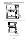
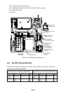
J106
J105
J104
J103
J446
J466
J462
J465
Screw
(M3X8, 5 pcs.)
*
*
*
*
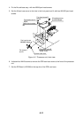
Slide forward
↓
Screw (M4X8, 2 pcs.)
Knob
Filter
(Shown:
AC type)
PTU Board (behind shield cover)
Power cable
leads
*
Unfasten
screws.
Figure 4-15 Processor unit, inside view