


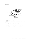

Command Module Site Preparation . . . . . . . . . . . . . . . . . . . . . . . . . . . . . . . . . . . . . . . . . . . . . . . . .
2-8 Command Module and Drive Module Site Preparation Guide
Power Requirements
This section provides information regarding command module AC power requirements,
power cord routing instructions, and site wiring conditions.
The AC power source must provide the correct voltage, current, and frequency specified
on the manufacturer’s nameplate. Internal AC power units for rackmount cabinets must
be able to handle the power requirements for these units (Table 2-7).
Power Cord Routing
All modules are shipped with two AC power cords that are appropriate for use in a typical
outlet in the destination country. Each power cord connects one of the power supplies in a
module to an independent, external power source, such as a wall receptacle or
uninterruptible power supply (UPS). If you have a rackmount cabinet with internal power
cabling, such as a ladder cable, you do not need these power cords.
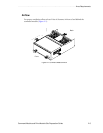
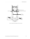
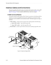
A rackmount cabinet can have up to two AC power distribution boxes with separate power
cords (Figure 2-3). To ensure redundancy, each power cord must connect to an
independent, external power source. Each AC power distribution box has a ladder cable
that runs up the inside of the cabinet and connects to one of the power supplies in each
module.
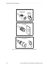
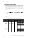
Figure 2-4 on page 2-10 shows the power cords and receptacles for domestic (inside USA)
and international use (outside USA).
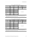
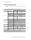
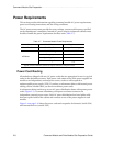
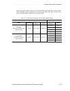
Table 2-7 Command Module Power Requirements
Item Unit of Measure Requirement
Circuit Breaker Slow-blow Fuse 3 A per Power Supply
AC Power
Nominal Voltage 90 to 264 VAC
Frequency 50 to 60 Hz
Operating Current
1 A
1
Maximum Surge Current
2 A
1
1
Typical current at 240 VAC, 60 Hz at 0.70 power efficiency, 0.99 power factor.