


Command Module and Drive Module Site Preparation Guide v
List of Figures
Chapter 1: 72-INCH CABINET SITE PREPARATION
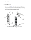
Figure 1-1. 72-inch Cabinet ........................................................................................................ 1-2
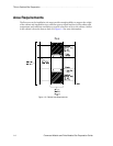
Figure 1-2. Cabinet Area Requirements ..................................................................................... 1-4
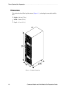
Figure 1-3. Cabinet Dimensions ................................................................................................. 1-6
Figure 1-4. Cabinet AC Distribution .......................................................................................... 1-9
Figure 1-5. Cabinet Ladder Cord .............................................................................................. 1-10
Figure 1-6. Types of 72-Inch Cabinet Power Cords and Receptacles ..................................... 1-11
Chapter 2: COMMAND MODULE SITE PREPARATION
Figure 2-1. Command Module Dimensions .............................................................................. 2-4
Figure 2-2. Command Module Airflow ..................................................................................... 2-5
Figure 2-3. Redundant Command Module AC Power Connections ....................................... 2-9
Figure 2-4. Types of 72-Inch Cabinet AC Power Cords and Receptacles .............................. 2-10
Figure 2-5. Optical and Copper GBICs .................................................................................... 2-12
Figure 2-6. SFP Transceiver and Fiber Optic Cable ................................................................ 2-14
Chapter 3: DRIVE MODULE SITE PREPARATION
Figure 3-1. FC-1 10x Drive Module Dimensions ...................................................................... 3-4
Figure 3-2. FC-1 14x and FC-2 14x Drive Module Dimensions ............................................... 3-5
Figure 3-3. Drive Module Airflow .............................................................................................. 3-6
Figure 3-4. Redundant AC Power Connections to Drive Modules ........................................ 3-10
Figure 3-5. Types of 72-Inch Cabinet AC Power Cords and Receptacles .............................. 3-11
Figure 3-6. Optical and Copper GBICs .................................................................................... 3-13
Figure 3-7. SFP Transceiver and Fiber Optic Cable ................................................................ 3-15
Chapter 4: ARRAY MODULE SITE PREPARATION
Figure 4-1. E2400 10x Array Module Dimensions .................................................................... 4-4
Figure 4-2. E2400 14x Array Module Dimensions .................................................................... 4-5
Figure 4-3. Array Module Airflow .............................................................................................. 4-6
Figure 4-4. Redundant AC Power Connections to Array Modules .......................................... 4-9
Figure 4-5. Types of 72-Inch Cabinet AC Power Cords and Receptacles .............................. 4-10
Figure 4-6. Optical and Copper GBICs .................................................................................... 4-12