


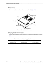
Command Module Site Preparation . . . . . . . . . . . . . . . . . . . . . . . . . . . . . . . . . . . . . . . . . . . . . . . . .
2-12 Command Module and Drive Module Site Preparation Guide
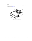
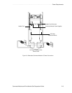
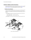
Interface Cables and Connections
This section provides information about command module interface cables, such as GBIC
minihubs and SFP transceivers, and their appropriate connections. See Figure 2-5 and
Figure 2-6 on page 2-14 for command module interface connector examples.
E4400 Command Module
The E4400 command module supports Fibre Channel connections to both hosts and drive
modules. Up to four host minihubs and four drive minihubs, for a maximum of eight
connections, can be installed in each command module. The E4400 supports two types of
minihubs:
•
GBIC minihub – contains a pair of connectors for attaching either of the following:
•
Optical GBIC module – used with fiber optic cable
•
Copper GBIC module – used with copper fiber cable
•
DB-9 minihub – contains a pair of DB-9 connectors for attaching copper fiber cable
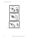
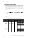
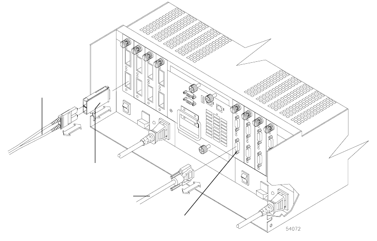
Figure 2-5 Optical and Copper GBICs
Copper Fiber Cable
DB-9 Connector
Fiber Optic or
Copper Fiber Cable
GBIC Module