


. . . . . . . . . . . . . . . . . . . . . . . . . . . . . . . . . . . . . . . . . . . . . . . . . . . . . . Environmental Requirements
Command Module and Drive Module Site Preparation Guide 3-7
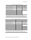
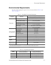
Environmental Requirements
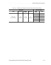
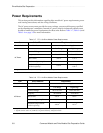
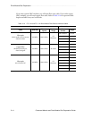
The drive module is designed to operate in the environment defined in Table 3-5 and
Table 3-6 on page 3-7.
Table 3-5 Drive Module Environmental Requirements
Condition Parameter
Requirement
FC-1 10x, FC-1 14x, and FC-2 14x
Temper ature
Operating Range
10
°
C to 40
°
C (50
°
F to 104
°
F)
Maximum Rate of Change
10
°
C (18
°
F) per hour
Storage Range
-10
°
C to 50
°
C (14
°
F to 122
°
F)
Maximum Rate of Change
15
°
C (27
°
F) per hour
Transit Range
-40
°
C to 60
°
C (-40
°
F to 140
°
F)
Maximum Rate of Change
20
°
C (36
°
F) per hour
Relative Humidity
No condensation
Operating Range 20% to 80%
Storage Range 10% to 90%
Transit Range 5% to 95%
Maximum Dew Point
26
°
C (79
°
F)
Maximum Gradient 10% per hour
Sound
Sound Power 6.0 bels
Sound Pressure 60 dBA
Altitude
(Above Sea Level)
1
Operating and Storage 3000 m (9840 ft.)
Transit 12,000 m (40,000 ft.)
Altitude
(Below Sea Level)
Operating, Storage, and Transit 30.5 m (100 ft.)
1
If you plan to operate a drive module at altitudes between 1000 m to 3000 m (3280 ft. to 9850 ft.) above sea level,
lower the environmental temperature 1.7
°
C (3.3
°
F) for every 1000 m (3280 ft.) above sea level.
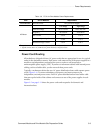
Table 3-6 Drive Module Heat Dissipation
Model
Low Profile (LP)
18 GB and 36 GB Drives
Half Height (HH)
36 GB and 73 GB Drives
FC-1 10x 1036 Btu/hr (0.306 kVA or 303 W) 1070 Btu/hr (0.33 kVA or 313 W)
FC-1 14x 1050 Btu/hr (0.309 kVA or 306 W) Not applicable.
FC-2 14x 1084 Btu/hr (0.320 kVA or 317 W) Not applicable.