


E6581429
B-4
2
2.3 Description of terminals
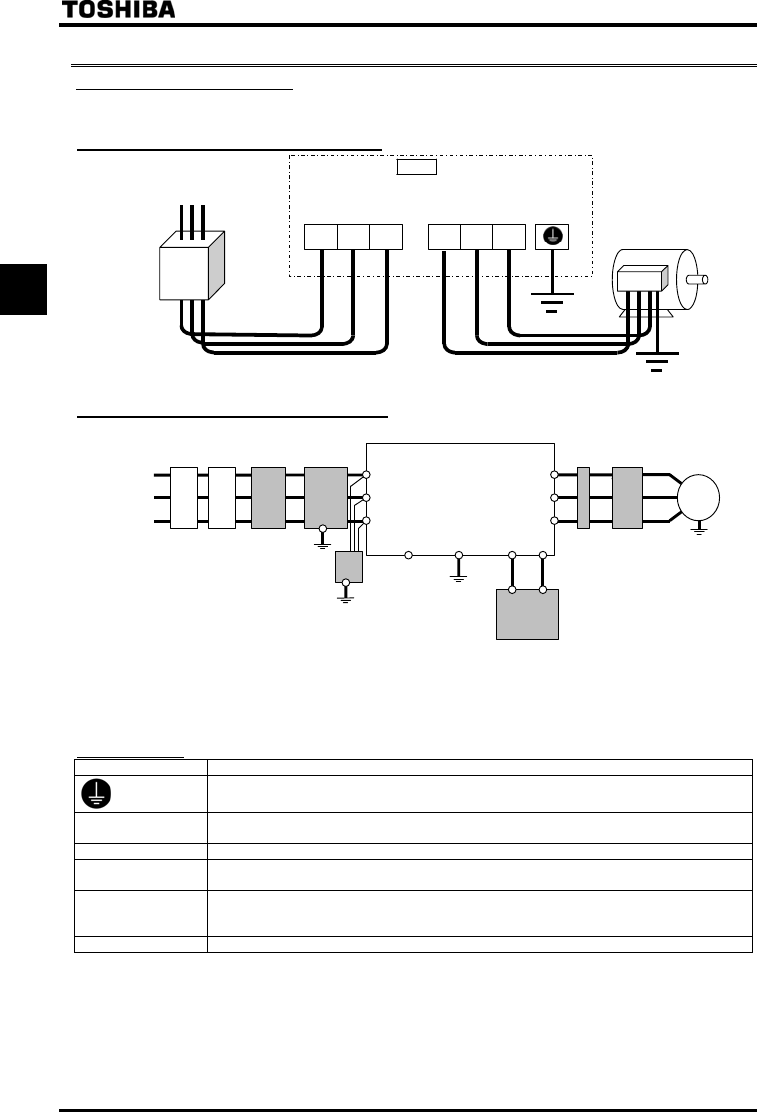
2.3.1 Main circuit terminals
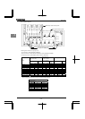
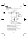
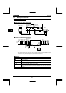
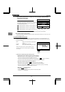
This diagram shows an example of wiring of the main circuit. Use options if necessary.
Q Power supply and motor connections
Power supply
S/L2 T/L3
Motor
No-fuse
breaker
Connect the power
cables to RL1, S/L2,
and T/L3.
Connect the motor
cables to U/T1, V/T2
and W/T3.
VF-PS1
E
U/T1
V/T2 W/T3
R/L1
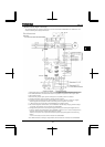
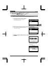
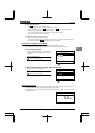
Q Connection with peripheral equipment
Motor
Zero-phase
reactor
Power
supply
Inverter
Braking resistor [Note]
Surge
su
pp
ressin
g
filter
Simplified
radio noise
filter
High-attenuation
radio noise
reduction filter
Input AC
reactor
Magnetic
contactor
No-fuse
breaker
R/L1
S/L2
T/L3
P0
PA/+
PB
V/T2
U/T1
W/T3
IM
Note) This inverter have DC reactor included, and have advantage of reducing input current, reducing harmonics and
power factor improvement. So, no DC reactor option is available. In case of requirement of additional reduction
of harmonics or more power factor improvement, input AC reactor is recommended.
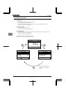
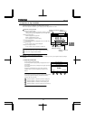
Q Main circuit
Terminal symbol Terminal function
Grounding terminal for inverter casing
R/L1, S/L2, T/L3
Power input terminal
0.75~110kW Three-phase 380~480V-50/60Hz
U/T1, V/T2, W/T3 Connect to a (3-phase induction) motor.
PA/+, PB
Connect a braking resistor.
Change the parameters Pb, Pbr and PbCP if necessary.
PC/-
This is a negative potential terminal in the internal DC main circuit. DC power supply can be input
across the PA/+ terminals (positive potential). (For 400V-30kW or more models, an optional circuit
is needed to suppress a rush current.)
PO Do not use.
, PE