


E6581429
H-1
8
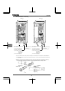
8. Selection of peripheral devices
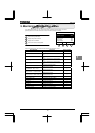
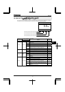
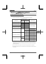
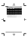
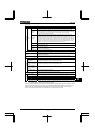
8.1 Selection of wiring materials and devices
Wire size
Main circuit
Input terminal
(R,S,T)
Output terminal
(U,V,W)
DC terminal
(optional)
Braking resistor /
Braking unit
(Optional)
Earth cable
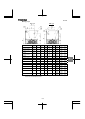
Applicable
motor
(kW)
Inverter type form
AWG mm
2
AWG mm
2
AWG mm
2
AWG mm
2
AWG mm
2
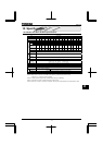
0.75 VFPS1-4007PLE/PDE 14 1.5 14 1.5 14 1.5 14 1.5 14 2.5
1.5 VFPS1-4015PLE/PDE 14 1.5 14 1.5 14 1.5 14 1.5 14 2.5
2.2 VFPS1-4022PLE/PDE 14 1.5 14 1.5 14 1.5 14 1.5 14 2.5
3.7 VFPS1-4037PLE/PDE 12 1.5 12 1.5 14 1.5 14 1.5 14 2.5
5.5 VFPS1-4055PLE/PDE 10 1.5 10 1.5 12 1.5 14 1.5 14 2.5
7.5 VFPS1-4075PLE/PDE 10 1.5 10 2.5 10 2.5 14 1.5 14 2.5
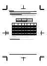
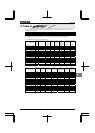
11 VFPS1-4110PLE/PDE 8 4 8 4 8 4 10 2.5 12 4
15 VFPS1-4150PLE/PDE 6 6 6 6 8 6 10 4 10 6
18.5 VFPS1-4185PLE/PDE 6 6 6 6 6 10 8 6 10 6
22 VFPS1-4220PLE/PDE 6 10 6 10 4 16 8 10 10 10
30 VFPS1-4300PLE/PDE 4 16 4 16 4 25 4 16 4 16
37 VFPS1-4370PLE/PDE 3 25 3 25 2 25 4 25 4 16
45 VFPS1-4450PLE/PDE 1 25 1 25 1 35 3 25 4 16
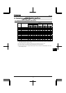
55 VFPS1-4550PLE/PDE 1/0 35 1/0 35 2/0 50 2 35 2 35
75 VFPS1-4750PLE/PDE 3/0 70 3/0 70 4/0 95 1/0 70 2 35
90 VFPS1-4900PLE/PDE 250MCM 95 250MCM 70 250MCM 120 2/0 95 2 50
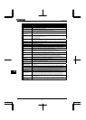
(*1): The recommended cable size is that of the cable (e.g. 600V class, HIV cable) with continuous maximum
permissible temperature of 75°C. The ambient temperature is assumed to be 40°C or below. (The interconnect
cable length is assumed to be 30m or less.)
(*2): For the control circuit, use shielded wires whose size (cross-section) is 0.75mm
2
or more.
(*3): For the earth cable, use wires larger than the specified ones in size (cross-section).
(*4): Recommended wire size for an optional braking resistor. Refer to instruction manual E6581386 5.19 for use of
external braking resistor.