


E6581429
G-2
7
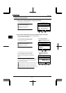
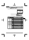
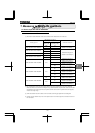
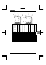
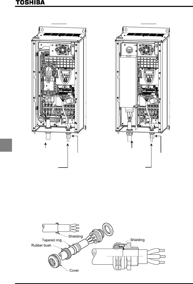
Q Ex. Countermeasure – inverter wiring
PLE - type PDE - type
Power supply wiring (Shielded cables) Power supply wiring (Shielded cables)
R/L1, S/L2, T/L3 Motor wiring (Shielded cables) R/L1, S/L2, T/L3 Motor wiring (Shielded cables)
(Fix with nonmetal cable gland) U/T1, V/T2, W/T3 (Fix with nonmetal cable gland) U/T1, V/T2, W/T3
(Fix with metal cable gland) (Fix with metal cable gland)
Control wiring (Shielded cables) Control wiring (Shielded cables)
Login input/output +SU, F, R, S1~S3 Login input/output +SU, F, R, S1~S3
RES, PWR, NO, RES, PWR, NO,
P24/PLC, OUT1, P24/PLC, OUT1,
OUT2, CC OUT2, CC
(Fix with nonmetal cable gland) (Fix with nonmetal cable gland)
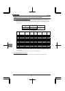
Note1) For cables other than above, refer to the example of countermeasure in instruction manual E6581386 9.1.2.
Note2) Wiring port plate have holes only for cables listed in above. In case of wiring other cables, please add hole for
each cable.
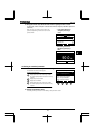
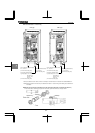
Q Mounting and connecting the shielded motor cable with metal cable gland (not supplied with the drive)
Fix the motor cable to the wiring port plate with metal cable gland with reference to the figure below.