


E6581429
G-4
7
7.2 Measurements to be taken to satisfy the UL/CSA standards
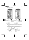
7.2.1 Caution as to peripheral devices
When installing a no-fuse circuit breaker or a fuse box on the primary side of the inverter, use UL-certified one.
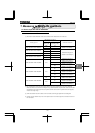
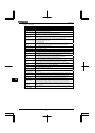
The UL certification test on this inverter was conducted under the AIC* conditions shown in table below (*: current
that flows in the event of a short-circuit in the power supply). Note that AIC currents vary depending on the capacity
of the motor used.
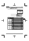
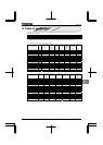
AIC and maximum input voltage
Applicable motor
(kW)
AIC
(A)
Maximum input voltage
(V)
0.4 ~ 37 5,000
45 ~ 90 10,000
480
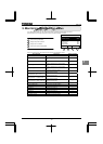
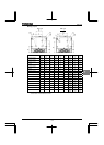
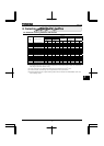
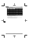
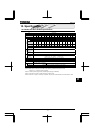
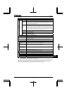
AIC, Fuse and Wire sizes
Applicable
motor
(kW)
Inverter type form
UL
Output current(A)
*1, *2
AIC (A)
(Interrupting
capacity)
Fuse class and
current (A)
Input wire size
of power circuit
(AWG)
*3
Output wire size
of power circuit
(AWG)
*3
Grounding
wire
(AWG)
*3
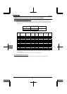
0.75 VFPS1-4007PLE/PDE 2.1 (CF=8) AIC 5000A CC 6Amax
.
14 14 14
1.5 VFPS1-4015PLE/PDE 3.4 (CF=8) AIC 5000A CC 6Amax
.
14 14 14
2.2 VFPS1-4022PLE/PDE 4.8 (CF=8) AIC 5000A CC 12Amax. 14 14 14
3.7 VFPS1-4037PLE/PDE 7.6 (CF=8) AIC 5000A J 15Amax. 12 12 14
5.5 VFPS1-4055PLE/PDE 11.0 (CF=8) AIC 5000A J 25Amax. 10 10 12
7.5 VFPS1-4075PLE/PDE 14. 0 (CF=8) AIC 5000A J 40Amax. 10 10 12
11 VFPS1-4110PLE/PDE 21.0 (CF=8) AIC 5000A J 40Amax. 8 8 10
15 VFPS1-4150PLE/PDE 27.0 (CF=8) AIC 5000A J 60Amax. 6 6 10
18.5 VFPS1-4185PLE/PDE 34.0 (CF=4) AIC 5000A J 70Amax. 6 6 10
22 VFPS1-4220PLE/PDE 40.0 (CF=4) AIC 5000A J 70Amax. 6 6 10
30 VFPS1-4300PLE/PDE 52.0 (CF=4) AIC 5000A J 80Amax. 4 4 10
37 VFPS1-4370PLE/PDE 65.0 (CF=4) AIC 5000A J 90Amax. 3 3 8
45 VFPS1-4450PLE/PDE 77.0 (CF=4) AIC 10000A J 110Amax. 1 1 8
55 VFPS1-4550PLE/PDE 96.0 (CF=4) AIC 10000A J 150Amax. 1/0 1/0 6
75 VFPS1-4750PLE/PDE 124.0 (CF=4) AIC 10000A J 175Amax. 3/0 3/0 6
90 VFPS1-4900PCE/PDE 156.0 (CF=4) AIC 10000A J 225Amax. 250MCM 250MCM 2
*1: UL output current is different from unit rating output current.
*2: The value of the UL rated output current is applicable when the carrier frequency (CF) is less than the value
shown in the table.
*3: The cables used must be 75°C copper cables within 40°C ambient temperature.
7.2.2 Conforming to UL Type 12
Drives with UL Type 12 conformity are optional. Contact your nearest Toshiba inverter distributor for them.