


05509F DCN6409 21
4. GETTING STARTED
The Model 465 is shipped with the following standard equipment:
Power cord (Rack mount version only)
Instruction manual.
Upon receiving the Model 465 please do the following:
1. Verify that there is no apparent shipping damage. (If damage has occurred please advise
shipper first, then Teledyne API.)
2. When installing the Model 465, allow a minimum of 4 inches for clearance at the back of
the instrument (rack mount only) and 1 inch of clearance on each side for proper
ventilation.
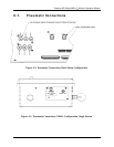
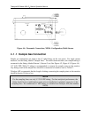
3. Connect sample inlet line(s) to the sample port on rear panel or bottom panel of
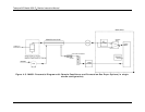
instrument. See Figure 4-2 or Figure 4-3 for rear panel pneumatic connections.
CAUTION
Connect the exhaust fitting on the rear panel (See Figure 4-2) to a suitable
vent outside the monitor area.
4. Ensure that there are no communication devices connected until after start-up is
complete.
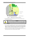
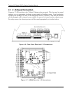
5. For the NEMA configuration, the electrical connection must be hard-wired to the 3-pin
connector on the mainboard labeled J23. AC power connection to the monitor should be
made with 12-14 AWG stranded copper wire, connected to the monitor as follows:
Earth Ground (green): Connect the earth ground wire to the screw terminal lug on the
chassis as shown in the Figure below. Do not connect the earth
ground wire directly to the PCB connector on the mainboard PCB.
Line (Black): Connect the Line wire to the connector on the mainboard PCB
labeled “Line”.
Neutral (White): Connect the Neutral wire to the connector on the mainboard PCB
labeled “Neutral”.
NOTE
Sample tubing made from an inert material such as Teflon should
be used to minimize sample degradation.