


Teledyne API Model 465L O
3
Monitor Operation Manual
72 05509F DCN6409
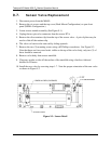
9.7. Sensor Valve Replacement
1. Disconnect power from the M465L.
2. Remove the six screws and the top cover (Rack Mount Configuration) or open front
panel (NEMA Configuration.)
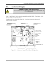
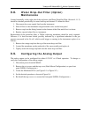
3. Locate sensor module assembly (See Figure 9-1.)
4. Unplug the two-pin valve connector from the sensor PCA.
5. Remove the silver retainer clip from the top of the sensor valve. A pair of pliers may be
used to slide off the retainer clip.
6. The valve coil can now be removed by sliding upwards.
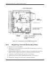
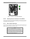
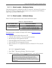
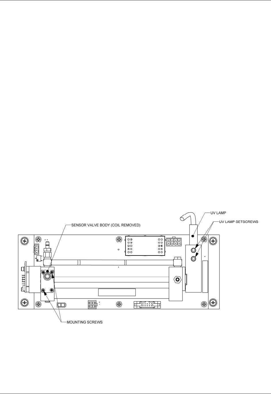
7. Remove the two (2) mounting screws using a #2 Phillips screwdriver. See Figure 9-3.
Note that there are four screw heads visible on the top of the valve body, only two (2) of
these should be removed.
8. Remove valve body from sensor manifold.
9. Clean any residue or dirt off the surface of the manifold using a lint-free cloth and
distilled or DI water.
10. Install the new valve by reversing steps 1-7. Note the proper orientation of the new valve
as shown in Figure 9-3.
Figure 9-3: Sensor Detail