


05509F DCN6409 78
10. TROUBLESHOOTING
WARNING
RISK OF ELECTRICAL SHOCK. THE OPERATIONS OUTLINED IN THIS
CHAPTER ARE TO BE PERFORMED BY QUALIFIED MAINTENANCE
PERSONNEL ONLY!
10.1. Reference Drawings
The drawings contained in this section are for general reference and may be useful when
performing certain troubleshooting activities.
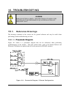
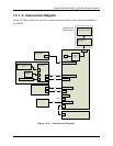
10.1.1. Pneumatic Diagram
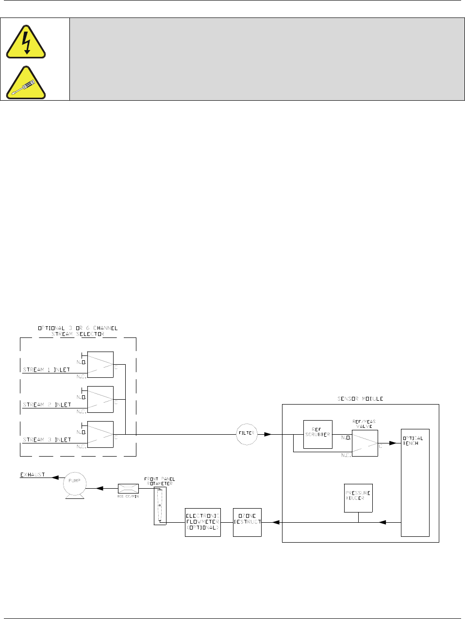
Figure 10-1 below is a pneumatic diagram that can be referenced when performing
troubleshooting on the monitor. Note that certain items, such as the Stream Selector and
Electronic Flowmeter are optional and will not be present in all M465L monitors.
Figure 10-1: Pneumatic Diagram, 3 Stream Configuration