


Teledyne API Model 465L O
3
Monitor Operation Manual
24 05509F DCN6409
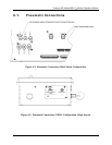
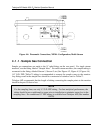
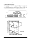
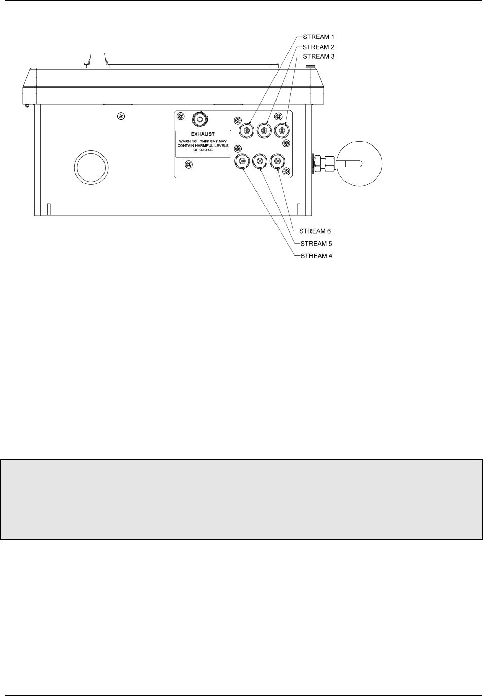
Figure 4-4: Pneumatic Connections, NEMA Configuration, Multi-Stream
4.1.1. Sample Gas Connection
Sample gas connections are made to the ¼” tube fittings on the rear panel. For single stream
monitors, use the fitting labeled “Sample Inlet.” For multi-stream monitors, the sample tubing is
connected to the fittings labeled Stream 1, Stream 2, etc (See Figure 4-2, Figure 4-3, Figure 4-4)
1/4" O.D. FEP (Teflon) tubing is recommended to connect the sample source to the monitor.
Any fittings used in the sample lines should be constructed of stainless steel or Teflon.
Teledyne API recommends that the length of tubing connecting the sample points to the monitor
should be kept to 50 feet or less.
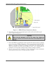
NOTE
For the sampling lines, use only ¼” O.D. FEP tubing. For best analytical performance, the
tubing should be pre-conditioned to ozone prior to installation to minimize ozone loss in the
sampling lines. Pre-conditioned ¼” FEP tubing is available from Teledyne API (Part number
02639)