


Teledyne API Model 465L O
3
Monitor Operation Manual
70 05509F DCN6409
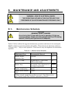
9.5. UV Lamp Replacement
CAUTION
GENERAL SAFETY HAZARD
Do not look at the UV lamp while the unit is operating. UV light can
cause eye damage. Always use safety glasses made from UV blocking
material. (Generic plastic glasses are not adequate).
WARNING - RISK OF ELECTRICAL SHOCK
HIGH VOLTAGE MAY BE PRESENT WHEN POWER IS CONNECTED TO
THE INSTRUMENT!
1. Disconnect power from the M465L.
2. Remove the six screws and the top cover (Rack Mount Configuration) or open front
panel (NEMA Configuration.)
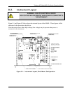
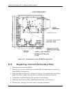
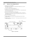
3. Loosen the two UV lamp setscrews on the UV lamp housing (see Figure 9-1 or Figure
9-2 above.)
4. Unplug the lamp power cord from the connector labeled P1 on the sensor module.
5. Loosen the four slotted captive screws attaching the sensor module to the chassis.
6. Carefully slide the lamp out of housing. The sensor module may need to be raised
slightly to completely remove the lamp.
7. Install the new lamp, seating it in the lamp housing until it stops.
8. Re-attach the sensor module captive screws to the chassis.
9. Re-tighten the two UV lamp setscrews.
10. Plug the lamp power cord into P1 on the sensor module.
11. Reconnect power to the instrument and turn on power switch. Let instrument warm up
for at least 20 minutes.
12. Perform UV lamp adjustment procedure per Section 9.4.
9.6. Sample Pump Replacement
1. Disconnect power from the M465L.
2. Remove the six screws and the top cover (Rack Mount Configuration) or open front
panel (NEMA Configuration.)
3. Locate sample pump assembly (See Figure 9-1.)
4. Cut off the clamps holding the tubing to the pump nipples and remove tubing. Note
which tubing is connected to inlet and outlet.