


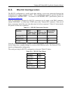
Teledyne API Model 465L O
3
Monitor Operation Manual
05509F DCN6409 57
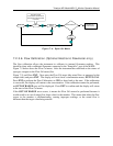
8.3. RS-232 Configuration
The RS-232 configuration is usually used when making a one-to-one connection between the
instrument and a single computer or PLC. The communications protocol used for the RS-232
configuration is MODBUS RTU. For details on the MODBUS RTU specification, please see
http://www.modbus.org/.
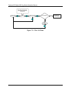
With the instrument configured for RS-232, connection can be made to the DB-9 connector,
labeled “RS232/485”, or to the three “COM” pins on the “General I/O” connector. Only one of
these connections should be used, the other must be left un-connected. Table 8-1 below details
the pinouts of these two connectors:
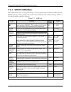
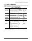
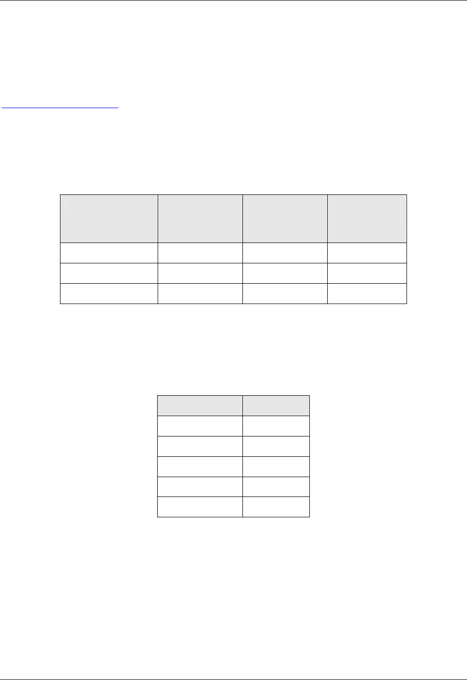
Table 8-1: RS-232 Connector Details
Function DB-9
Connector Pin
(SW2 – DTE)
DB-9
Connector Pin
(SW2 – DCE)
General I/O
Connector
Transmit (Tx) 3 2 ‘T’
Receive (Rx) 2 3 ‘R’
Ground 5 5 ‘G’
Note that a DTE-DCE switch is provided so that the instrument can be connected to another
device using either a straight-through or crossover (Null-Modem) cable. See Section 8.2 for
details on changing this configuration.
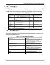
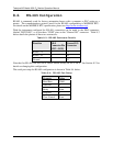
The serial port setup for RS-232 configuration is shown in Table 8-2 below:
Table 8-2: RS-232 Port Setup
Property Value
Baud Rate 57600
Data Bits 8
Parity None
Stop Bits 1
Flow Control None