


Teledyne API Model 465L O
3
Monitor Operation Manual
05509F DCN6409 31
4.2.4. Hi-Current Relay Outputs
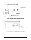
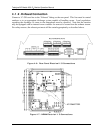
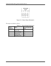
Three form C relay outputs are provided on the rear panel on the nine pin connector (See Figure
4-6). The relays are labeled “Relay 1,” “Relay 2,” and “Relay 3.”
The relays are dry contact type form C (SPDT) relays with Normally Open (N.O.), Normally
Closed (N.C.) and Common (COM) contacts. The relays are capable of driving loads of up to
250VAC, 5A. For maximum contact life, the relays should only be used to drive resistive loads.
Contact life may be dramatically shortened if inductive loads are driven without any provision
for minimizing high voltage “inductive kick” that can occur.
These relays have slightly different functions depending on whether the monitor is a single
stream or multi-stream configuration.
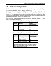
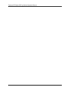
Table 4-2: Relay Functions for Single Stream Config
Relay # Function Normal
Operating State
1 System OK Diagnostic On
2 Hi Alarm Off
3 Hi-Hi Alarm Off
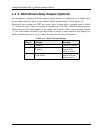
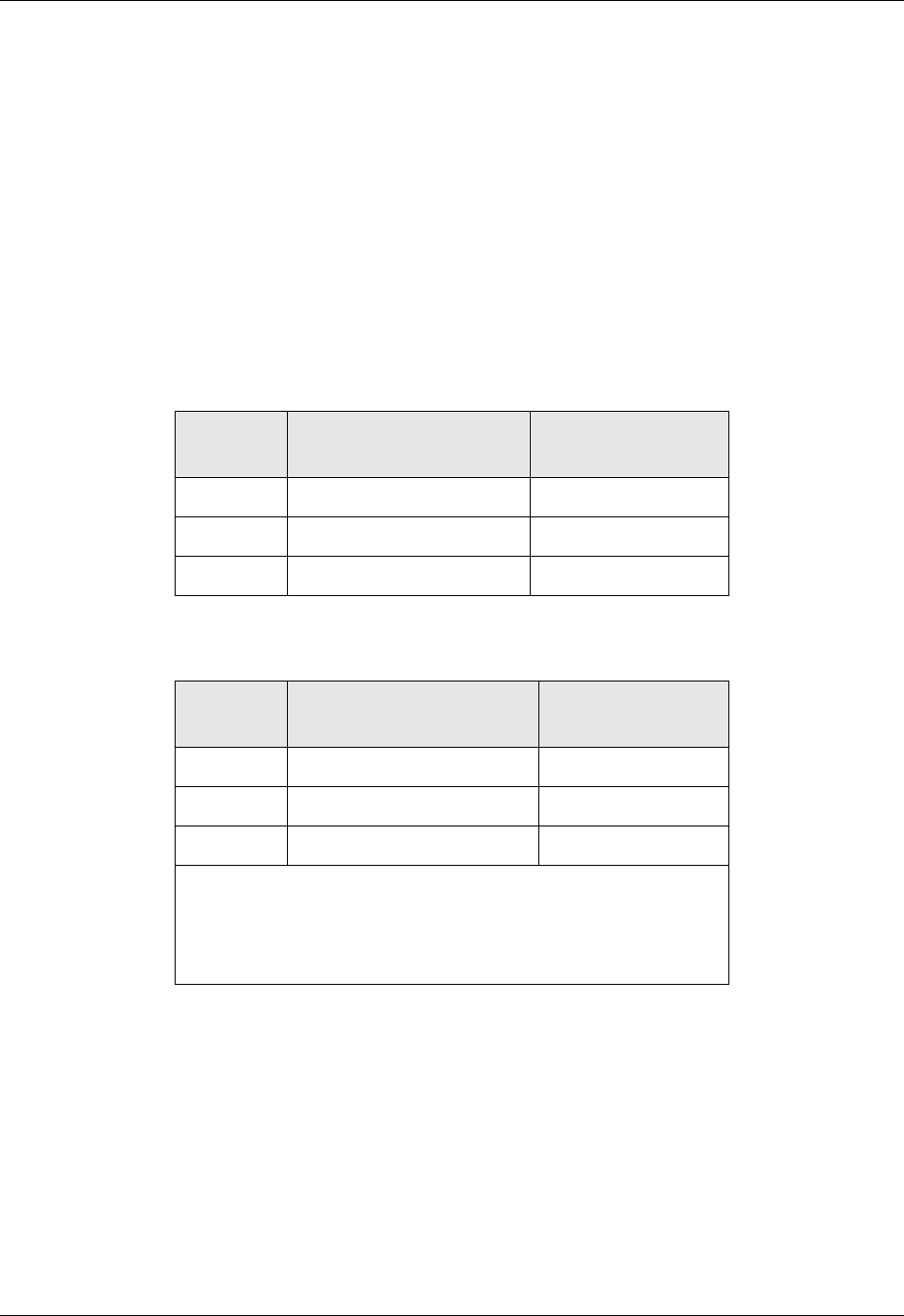
Table 4-3: Relay Functions for Multi-Stream Configs
Relay # Function Normal
Operating State
1 System OK Diagnostic On
2 Global Hi Alarm* Off
3 Global Hi-Hi Alarm* Off
* The state of the global alarm represents all the Hi or
Hi-Hi alarm states OR’d together, i.e. if the Hi alarm for
one or more of the sample streams is activated, then the
Global Hi alarm will be activated.