


TS-440S
CIRCUIT DESCRIPTIO
N
3
.
Transmitter Circuit Descriptio
n
IC
4
MIC
pPCI
I58HZ
SS
B
D
<M1C AMP
GAI
N
PRO
C
FSK
IN
45
.05^
-
75
.05MH
z
Q4
6
3SK73
Q10,1
I
3SK122 x2
Q13,1
4
3SKI22x
2
F
I
MC
F
Q4
4
2SC2459
IC
5
AN612
CFI
IC
6
AN612
CF
4
IST
MIX
9
.83MH
z
DB
M
ssB
Q1
6
2SC253
8
LP
F
Q
I
2SC2075
02,3
Q4,
5
2SC2509x2 2SC2879x 2
LPF/
-
0
A
.T
R
X
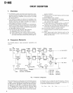
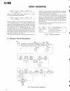
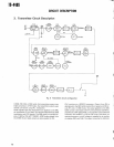
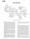
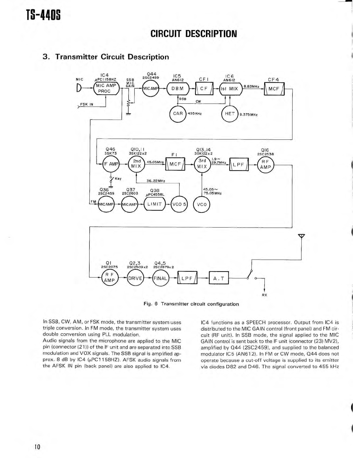
Fig
. 6 Transmitter circuit
configuratio
n
In SSB, CW, AM, or FSK mode, the transmitter system use
s
triple conversion
. In FM mode, the transmitter system use
s
double conversion using PLL modulation
.
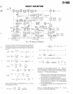
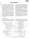
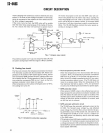
Audio signals from the microphone are applied to the MI
C
pin (connector (21)) of the IF unit and are separated into SS
B
modulation and VOX signals
. The SSB signal is amplified ap-
prox
. 8 dB by IC4 (µ
.PC 1 1 58HZ)
. AFSK audio signals fro
m
the AFSK IN pin (back panel) are also applied to IC4
.
IC4 functions as a SPEECH processor
. Output from IC4 i
s
distributed to the MIC GAIN control (front panel) and FM cir-
cuit (RF unit)
. In SSB mode, the signal applied to the MI
C
GAIN control is sent back to the IF unit (connector (23) MV2)
,
amplified by Q44 (2SC2459), and supplied to the balance
d
modulator IC5 (AN612)
. In FM or CW mode, Q44 does no
t
operate because a cut-off voltage is supplied to its emitte
r
via diodes D82 and D46 . The signal converted to 455 kH
z
10