


TS-440
S
CIRCUIT DESCRIPTIO
N
2)
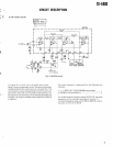
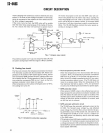
AF notch circuit
R OH
M
BX7I91— 851
8
123
10
BX719
I
R7 IOK
R9 22
K
OUT!
-
S
C
5
1
0
+
0 iI t
i
U
W
U
D27
D2
6
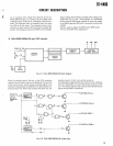
Fig
. 5 NOTCH circui
t
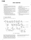
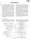
The hybrid ICI in the IF unit is an audio notch circuit
.
Figure 5 shows its equivalent circuit
. This circuit forms state-
variable band pass filter, also known as a bi-quad filter
. Th
e
notch frequency can be changed using the notch control vari
-
able resistor
. Since the circuit consists of the hybrid IC, sta
-
ble attenuation characteristics can be obtained electrically an
d
thermally
. The range of variable notch frequencies is 400 H
z
to 2600 Hz
.
The notch frequency is determined by the following tw
o
formulas
.
1)
f
N
,,R6/27r (R1 +Notch VR)•R8•R10•C1
.
C65
1
2)
R6
.
1R12+R13)=R10•R11
2
If a variable resistor is used for resistor NOTCH VR, the notc
h
frequency can be controlled according to formula 1)
.
The notch frequency range is from 400 to 2600 Hz, and at-
tenuation is from 25 to 50 dB
.
9