


TS-440
S
CIRCUIT DESCRIPTIO
N
4
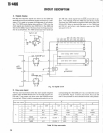
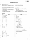
. Static input
7800 (ICI
)
C
O
C
2
07
Encoder U/D signa
l
Unlock signa
l
4052 (IC
: Display)
"H"
when U
P
"L"
when unloc
k
A/D convertor dat
a
8255 (IC53
)
B
O
B
2
B
3
B
4
B
5
B7
Lock switc
h
AT switc
h
MIC UP switc
h
MIC DOWN switc
h
PTT switc
h
VS-1 busy signal
"L"
when switch o
n
"L"
when switch o
n
"L"
when switch o
n
"L"
when switch o
n
"L"
when switch o
n
"H"
when VS-1 busy
6
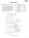
.
AT
control
L
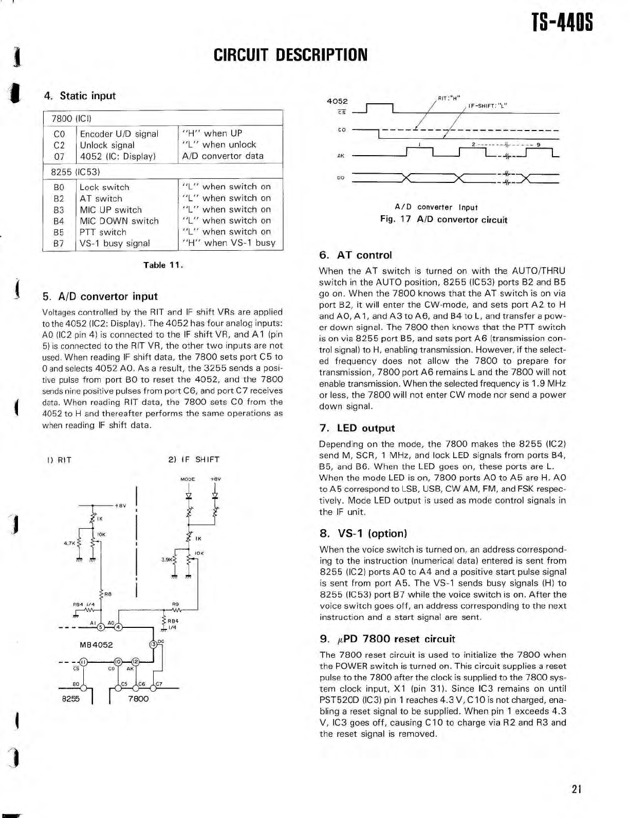
A/D
converter Inpu
t
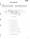
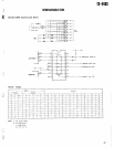
Fig
.
17
A/D convertor circui
t
2
9
--%---
1
A
K
D
O
I
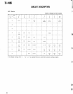
Table 1 1
.
5
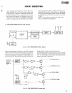
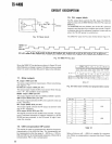
. A/D convertor inpu
t
Voltages controlled by the RIT and IF shift VRs are applie
d
to the 4052 (IC2
: Display)
. The 4052 has four analog inputs
:
AO (IC2 pin 4) is connected to the IF shift VR, and
Al
(pi
n
5) is connected to the RIT VR, the other two inputs are no
t
used
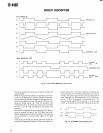
. When reading IF shift data, the 7800 sets port C5 t
o
0 and selects 4052 AO
. As a result, the 3255 sends a posi
-
tive pulse from port BO to reset the 4052, and the 780
0
sends nine positive pulses from port C6, and port C7 receive
s
data
. When reading RIT data, the 7800 sets CO from th
e
4052 to H and thereafter performs the same operations a
s
when reading IF shift data
.
When the AT switch is turned on with the AUTO/THR
U
switch in the AUTO position, 8255 (IC53) ports B2 and B
5
go on
. When the 7800 knows that the AT switch is on vi
a
port B2, it will enter the CW-mode, and sets port A2 to
H
and A0,
Al,
and A3 to A6, and B4 to L, and transfer a pow-
er down signal
. The 7800 then knows that the PTT switc
h
is on via 8255 port B5, and sets port A6 (transmission con-
trol signal) to H, enabling transmission
. However, if the select
-
ed frequency does not allow the 7800 to prepare fo
r
transmission, 7800 port A6 remains L and the 7800 will no
t
enable transmission
. When the selected frequency is 1.9 MH
z
or less, the 7800 will not enter CW mode nor send a powe
r
down signal
.
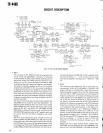
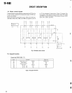
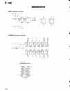
7.
LED outpu
t
Depending on the mode, the 7800 makes the 8255 (IC2
)
send M, SCR, 1 MHz, and lock LED signals from ports B4
,
B5, and B6
. When the LED goes on, these ports are L
.
When the mode LED is on, 7800 ports AO to AS are H
. A
O
to A5 correspond to LSB, USB, CW AM, FM, and FSK respec
-
tively. Mode LED output is used as mode control signals i
n
the IF unit
.
8.
VS-1 (option
)
When the voice switch is turned on, an address correspond-
ing to the instruction (numerical data) entered is sent fro
m
8255 (IC2) ports AO to A4 and a positive start pulse signa
l
is sent from port A5
. The VS-1 sends busy signals (H) t
o
8255 (IC53) port B7 while the voice switch is on
. After th
e
voice switch goes off, an address corresponding to the nex
t
instruction and a start signal are sent
.
9.
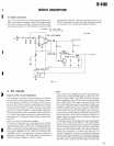
µPD 7800 reset circui
t
The 7800 reset circuit is used to initialize the 7800 whe
n
the POWER switch is turned on
. This circuit supplies a rese
t
pulse to the 7800 after the clock is supplied to the 7800 sys
-
tem clock input, X1 (pin 31)
. Since IC3 remains on unti
l
PST520D (IC3) pin 1 reaches 4.3 V, C10 is not charged, ena
-
bling a reset signal to be supplied
. When pin 1 exceeds 4
.
3
V, IC3 goes off, causing C10 to charge via R2 and R3 an
d
the reset signal is removed
.
I)
RIT
2) IF SHIF
T
MB 4052
2
1