


I
I
-
022
(
I
59
.55
...
67
.0
5
/J\
1114
.5
.22
1
Q
Q23 (
52
.55
5
1
1
(7
.5-14
.5
1
020
Q24 (
45
.05 52
.5
5
(0 ^ 7
.5
1
O
•
Q1
8
0
Q17
Q21
67
.05
75
.0
5
122
.
. 301
TS-440
S
I
CIRCUIT DESCRIPTIO
N
13
.
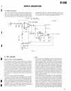
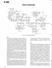
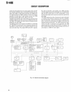
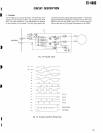
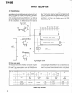
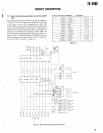
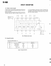
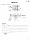
Band information generation circuit (in the R
F
unit
)
Band information from the control unit is sent to connecto
r
15 of the RF unit
. Band information signals BO to B3 for
m
a BCD code in which BO corresponds to LSB
. Q4
D
(M74LS145P) is used to convert data from BCD to DEC, an
d
it generates control signals for ten of the 11 bands
. Contro
l
signals for the remaining band (25
.5 MHz to 30 MHz) ar
e
generated in the AND circuit consisting of D57, D58, an
d
Q46
. These contorl signals go through the current buffer con
-
sisting of Q41 to Q45 (M54561P and 2SA562Y), and ar
e
OR'ed by diodes, as required, and sent to AT unit, filter unit
,
CO, and ANT BPF, as shown in Figure 21
.
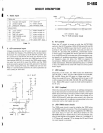
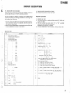
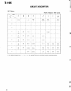
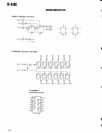
Band information 7800 PBo —
3,
B3B2B1B
o
30kHz -
0
.5MHz
0 0
0 0
0
.5MHz -
1
.6MHz 0 0
0
1
1
.6MHz -
2
.5MHz
0 0
1
0
2
.5MHz -
4MHz
0 0
1
1
4MHz -
6MHz
0 1
0 0
6MHz -
7
.5MHz
01
0
1
7
.5MHz -
10
.5MHz
01
1
0
10
.5MHz -
14
.5MHz
0 1
1
1
14
.5MHz -
22MHz
1 0 0 0
22MHz -
25
.5MHz
1
00
1
25
.5MHz -
30MHz
1 0 1
0
Table 1
3
I4
V
Q40 M74LS145P
BCD
—
DEC
V
v
0
Q41 M54561P Buff
\/
x
0
0
0
0
042 Q43 Q44
l
D6
0
~~6
1
D6
5
D64
0I
D63
N
1
28F
122
,
-, 30
)
21F
(14
.5-- 22
)
141
17
.5-- 14
.5
1
71'
(47-7
.5
1
4F
(2
.5^
,
4
,
2F
11
.6-- 2
.5)
To Filter
u
D62
28T
(25
.5
.
30
1
24T
122
25
.5
1
IT
114
.5-
221
To AT
u
I4T
110
.5--
14
.5
1
1OT
17
.5 '
10
.5
1
7T
(6
~
..
7
.51
0
1
0
0
0
VCO SW VC
O
To RFU BP
F
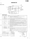
Fig
. 21 Band information generation circuit
2 3