


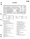
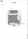
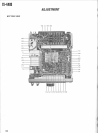

TS-440S
ADJUSTMEN
T
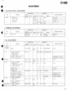
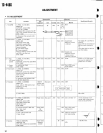
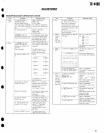
• TX
ADJUSTMEN
T
Measurement
Adjustmen
t
Item
Condition
Tes
t
equipment
Unit
Terminal
Unit
Part
Method
Specification/Remark
s
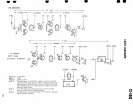
1
. TX AMPM
1) FREQ
: 14
.1750 MH
z
MODE
: C
W
CAR LEVEL control
: MA
X
RF unit VR 4
: CENE
R
Disconnect DRV connector from RF
Oscilloscope
RF
DRV
RF
VR
5
T13
,
16,
17
MA
X
unit
. Then, connect as shown right
.
STBY
: SEND
C
t
SCILL
O
5612
SCOP
E
2)
Reconnect this connector afte
r
adjustment
.
(1/4W
)
2
.
Base Current
1) FREQ
: 14
.1750 MH
z
MODE
: US
B
MIC LEVEI control
: MI
N
CAR LEVEL control
: MI
N
FINAL unit VR1, VR2
: MI
N
Connect Ammete
r
Q+
: EXT Power suppl
y
e
:
Power connecto
r
Adjust to minimum current with VR
1
and VR2 in the Final unit
.
STBY
: SEND
Ammeter
Final
VR1
Current drai
n
(Minimum current
)
+200 mA
First adjust VR1 and VR2 fo
r
minimum
.
Adjust VR1 for an increase o
f
200 mA when switched t
o
TX
.
Then adjust VR2 for 200 m
A
over this reading
.
VR2
Current drai
n
(Minimum current
)
+Driver curren
t
(200 mA)+200 m
A
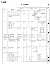
3
.
1)
AL
C
(RF Outpu
t
power
)
2) Powe
r
meter
1) FREQ
: 14
.1750 MH
z
MODE
: C
W
CAR LEVEL control
: ALC scale MA
X
STBY
: SEND
Power meter
Rear panel
ANT
Filter
VR1
95 W
Caution
:
In no case shoul
d
the power be adjusted fo
r
greater than 110 watts
.
VR6
Set to PWR mete
r
95 W readin
g
2) METER SW
: PW
R
STBY
: SEN
D
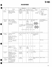
4
. Power down
1) FREQ
: 29
.7000MH
z
MODE
: C
W
CAR LEVEL control
: ALC scale MA
X
Connect ACC socket pin (PD) t
o
50 W from NC
.
STBY
: SEND
Power meter
Filter VR3
50 W
±2
.5
W
2)
Reconnect this connector (PD
)
to NC after adjustment
.
5
.
Protection
1) FREQ
: 14
.2000MH
z
MODE
: C
W
Coax
. cable to 1 500 dummy loa
d
should be 1 m long
.
STBY
: SEND
1504 R
F
dummy loa
d
Power meter
Rear panel
AN
T
I
Filte
r
1 m
VR2
1
30
W
m
TX
Pow
.M
50
4
I I
2) ANT
: OPEN
18A or les
s
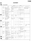
6
. ALC meter
1) FREQ
: 14
.2000 MHz
Power meter
Rear panel
ANT
Filter
VR4
Set to S meter
"0"
*If this adjustment is per
-
MODE
: USB
formed, step 2) Base curren
t
MIC LEVEL control
: MIN
must also be performed
.
CAR LEVEL control
: MI
N
METER SW
: AL
C
STBY
: SEN
D
2) Connect the AG to MIC Jack
.
AG
: 1 kHz, 5 m
V
STBY
: SEND
Power mete
r
A
G
AF VM
Filter
VR4
Set to ALC mete
r
starting point
.
3) AG
: 6 dB increase leve
l
(1 kHz, 10 mV)
VR5
Adjust for maximu
m
ALC scale reading
AL
C
7
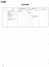
.
Spurious
FREQ
: 21
.2000 MHz
Power meter
RF
VR4
-40
dB or less
.
MODE SW
: C
W
CAR LEVEL control
: ALC scale MA
X
STBY
: SEND
Spectru
m
analyzer
MIN
94
0
I
/
/