


TS-440S
CIRCUIT DESCRIPTIO
N
14
.
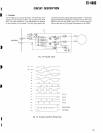
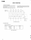
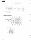
Mode control signal
s
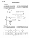
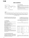
Transmit/receive mode signals are generated by ICI 0 in the
to 10, the voltages of control pins 16 and 17 change
. Dur
-
IF unit
. IC 10 is a hybrid IC containing five pairs of PNP tran-
ing reception, these signals change to SSR, CWR, RYR, AMR
,
sistors and diodes
.
and FMR
. During transmission, these signals change to SST
,
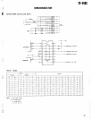
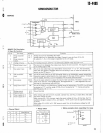
Figure 22 shows its equivalent circuit
. When the mode sig-
CWT, RYT, AMT, and FMT
.
nals SSB, CWB, RYB, AMB, and FMB are applied to pins
6
~ t
t
LL LL
4
F
Q Q
2
H
3
3
C>
V
BX6124
Fig
. 22 Mode control circuit
L
15
.
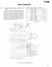
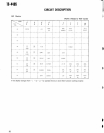
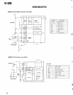
Expand functio
n
Control unit (X53-1450- 11
D No
.
Shipped
Diode cu
t
65
Mode beep tone
Morse
Single ton
e
66
10Hz display
OFF
O
N
67
Memory protect
OFF
O
N
73
CW shift
800Hz
400H
z
78
W 24
TX
No
Ye
s
79
W 18
TX
No
Yes
Table 14 Expand function
I
24