


TS-440S
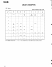
CIRCUIT DESCRIPTIO
N
10
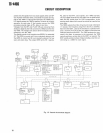
. PLL output bloc
k
The PLL output block controls five PLL loops
. The 500 kH
z
step PLL loop uses an MB87006 and the other PLL loops us
e
PES
MN6147s
.
,uPD7800
The M387006 has two dividers
: one for the PLL referenc
e
frequency and the other for a swallow type counter
. Frequen
-
cy division data for the reference frequency is sent only on
e
when the TS-440 power is switched on
.
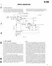
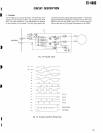
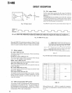
Fig
. 18 Reset circuit
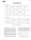
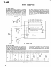
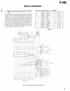
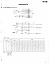
The MN6147 uses the PLL data format shown figure 19
.
8255(
IC
)
Por
t
B4n,B
7
BO
r
B3
Address
Fig
. 19 MN6147 PLL dat
a
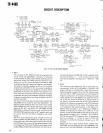
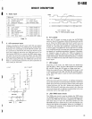
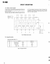
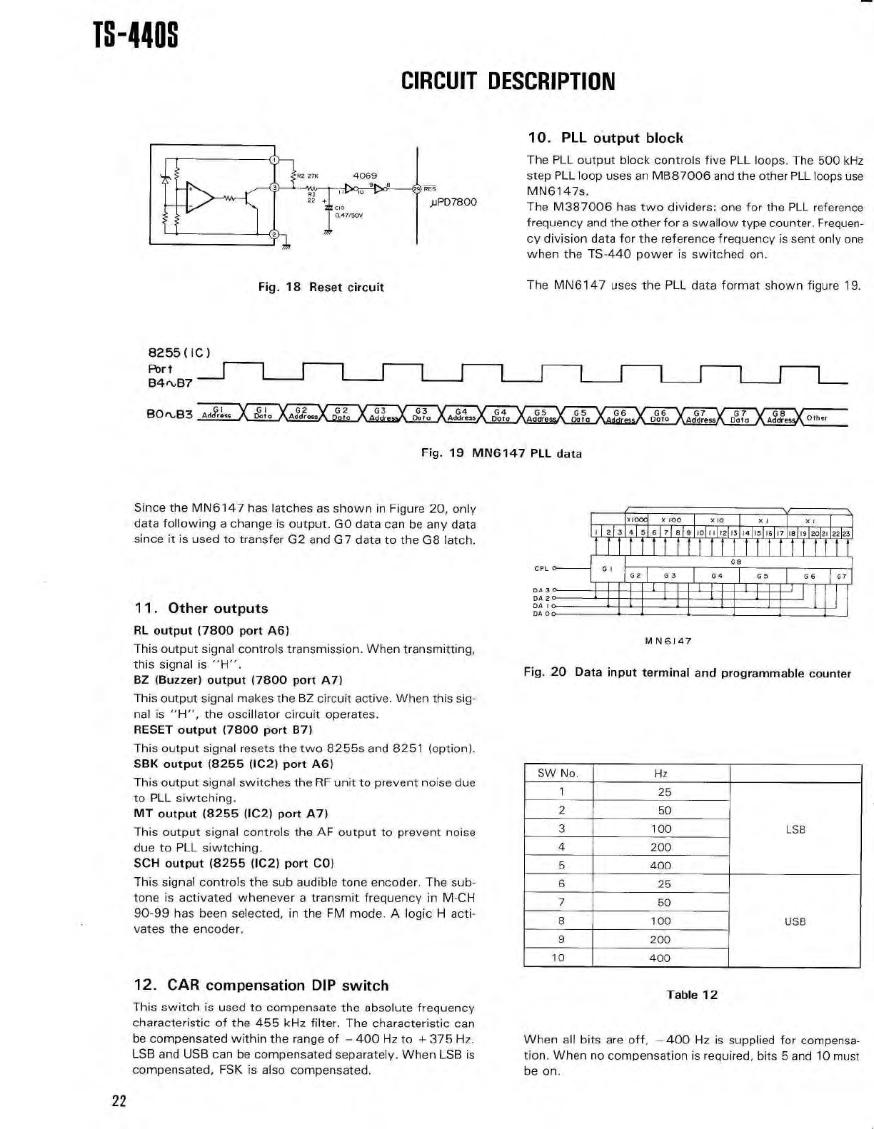
Since the MN6147 has latches as shown in Figure 20, onl
y
data following a change is output
. GO data can be any dat
a
since it is used to transfer G2 and G7 data to the G8 latch
.
11.
Other output
s
RL output (7800 port A6
)
This output signal controls transmission. When transmitting
,
this signal is "H"
.
BZ (Buzzer) output (7800 port A7
)
This output signal makes the BZ circuit active
. When this sig
-
nal is "H", the oscillator circuit operates
.
RESET output (7800 port B7
)
This output signal resets the two 8255s and 8251 (option)
.
SBK output (8255 (IC2) port A6
)
This output signal switches the RF unit to prevent noise du
e
to PLL siwtching
.
MT output (8255 (IC2) port A7
)
This output signal controls the AF output to prevent nois
e
due to PLL siwtching
.
SCH output (8255 (IC2) port CO
)
This signal controls the sub audible tone encoder
. The sub
-
tone is activated whenever a transmit frequency in M-C
H
90-99 has been selected, in the FM mode
. A logic H acti-
vates the encoder
.
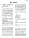
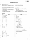
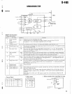
12.
CAR compensation DIP switc
h
This switch is used to compensate the absolute frequenc
y
characteristic of the 455 kHz filter
. The characteristic ca
n
be compensated within the range of — 400 Hz to + 375 Hz
.
LSB and USB can be compensated separately
. When LSB i
s
compensated, FSK is also compensated
.
coo x
+
100
xi0
xi
xi
-
le©©II~11
IINI
m®®m®mlllImm
AE
I
111111111111111111111
1
MIm
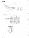
G
B
G3
G4
GS
G
G
.__
.-~i
2 3
MN 614
7
Fig
. 20 Data input terminal and programmable counte
r
SW No
.
H
z
1
2 5
2
5 0
3
100
LS
B
4
20
0
5
40
0
6
2 5
7
5
0
8
100
US
B
9
20 0
10
400
Table 1
2
When all bits are off,
-400
Hz is supplied for compensa-
tion
. When no compensation is required, bits 5 and 10 mus
t
be on
.
CP
L
DA
3
DA
2
DA
I
DA
0
22